Sbc oracle acme packet команды
This documentation provides instructions on how to configure an Oracle Acme Packet Session Border Controller (SBC) with ClearIP for outbound calls. After the SBC has been configured according to these instructions, then SIP INVITES can be sent to ClearIP.
The diagram below provides an overview of how ClearIP is configured as a SIP end point with an SBC. A SIP INVITE is sent from the CFS (Call Feature Server) to the SBC. Then the SBC forwards the INVITE to ClearIP for services, such as fraud and robocall control.
If no fraud is detected, ClearIP returns a SIP 404 No Route Found message and the SBC forwards the INVITE to the original destination. If fraud is detected, ClearIP responds with a SIP 603 Decline message indicating the call should be blocked. The SBC forwards the SIP 603 Decline message to the CFS. ClearIP can also return a SIP 302 Moved Temporarily message with an alternative destination if the call should be diverted.
Outbound network call flow

This documentation does not include SBC installation instructions, such as installing SBC VMware image, configuring network interfaces, etc. This work should be done by Oracle technical support.
Resiliency
Several features enable availability, a key component of a secure deployment.
It is strongly recommended that the SBC be deployed in a High Availability (HA) architecture with a Primary node and a Secondary node connected over both Wancom1 and Wancom2 interfaces for resiliency. It is also recommended that the two units in an HA pair be directly cabled together. While they can be separated and connected via an Ethernet switch or layer 2 VPN, this introduces latency and can significantly impact capacity. Since session replication is performed over a clear text connection, it may also expose call or configuration data sent in the replication process. In short, a geographically redundant pair of SBCs is not recommended. If geo-redundancy is an absolute requirement, a secure site-to-site VPN should be implemented for session replication, and thorough testing should be conducted to understand impacts to session capacity.
Guidelines are presented in “520-0011-03 BCP - High Availability Configuration”.
Configuration is detailed in Section 14 “High Availability Nodes” of the ACLI Configuration Guide.
Link Detection and Gateway Polling
If the gateway-heartbeat is enabled, the SBC periodically sends ARP requests for each configured network-interface gateway. If the configured number of retransmissions has been exceeded, the SBC will mark that gateway as unreachable and decrement its health score. If the health score decrements far enough, and the health score of the standby unit is higher, an HA failover will occur.
It is recommended that exactly one network-interface per physical interface have gateway-heartbeat enabled.
The following configuration fragment depicts the recommended default settings for the gateway heartbeat sub-element. It is also advisable to increment the health-score value by one with each new heartbeat configuration for ease of failure identification based on score.
The feature is explained in detail in the “High Availability Nodes” chapter of the ACLI Configuration Guide.
ACME Packet SBC 3800/4500: Name restrictions for manipulation rules Helper script for 6.2+ upgrades
ACME Packet / Oracle SBC releases 6.2 (and higher) introduce new restrictions applied to manipulation rules:
When upgrading a system running release 6.1 (or lower) with numerous existing rules, case warnings are generated. An example warning:
Existing rules continue working fine, but in order to maintain a clean system they should be corrected.
Manually fixing the names for hundreds of rules from the ACLI can be a tedious, intensive task. This brutal script attempts to simplify this operation by performing corrections against a configuration backup extracted from the session border controller and utilizing the exact warnings generated by the SBC itself (no guesswork/assumptions).
NOTE: The approach is best suited for preparation on a lab/spare system to generate the fixed configuration.
THIS SOFTWARE IS PROVIDED BY THE COPYRIGHT HOLDERS AND CONTRIBUTORS "AS IS" AND ANY EXPRESS OR IMPLIED WARRANTIES, INCLUDING, BUT NOT LIMITED TO, THE IMPLIED WARRANTIES OF MERCHANTABILITY AND FITNESS FOR A PARTICULAR PURPOSE ARE DISCLAIMED. IN NO EVENT SHALL THE COPYRIGHT OWNER OR CONTRIBUTORS BE LIABLE FOR ANY DIRECT, INDIRECT, INCIDENTAL, SPECIAL, EXEMPLARY, OR CONSEQUENTIAL DAMAGES (INCLUDING, BUT NOT LIMITED TO, PROCUREMENT OF SUBSTITUTE GOODS OR SERVICES; LOSS OF USE, DATA, OR PROFITS; OR BUSINESS INTERRUPTION) HOWEVER CAUSED AND ON ANY THEORY OF LIABILITY, WHETHER IN CONTRACT, STRICT LIABILITY, OR TORT (INCLUDING NEGLIGENCE OR OTHERWISE) ARISING IN ANY WAY OUT OF THE USE OF THIS SOFTWARE, EVEN IF ADVISED OF THE POSSIBILITY OF SUCH DAMAGE.
TLDR; USE AT YOUR OWN RISK!
Warning Extraction from SBC
Restore the backup to a Lab SBC running version 6.1 (suggested) or on your standby node.
Upgrade your standby SBC node to version 6.2 (or higher) then execute command 'verify config'
WARNING: element-rule [CLI] name contains invalid characters. Use characters that match the expression ^[[:alpha:]][[:alnum:]_]+$
WARNING: element-rule [FROM_URI_HOST] name contains invalid characters. Use characters that match the expression ^[[:alpha:]][[:alnum:]_]+$
WARNING: element-rule [FROM_URI_USER] name contains invalid characters. Use characters that match the expression ^[[:alpha:]][[:alnum:]_]+$
./aclean.sh warnings.txt backup_post_upgrade.gz
5. SBC configuration
This section provides details on the SBC configuration settings for operation with ClearIP for outbound call scenarios.
1. Outbound scenarios
ClearIP can be used for STIR/SHAKEN authentication, toll fraud prevention for outbound call scenarios and used for STIR/SHAKEN verification and robocall prevention for inbound call scenarios. In the inbound scenarios, SBC directly forwards the calls from source devices to ClearIP. In the outbound scenarios, SBC forwards the calls to ClearIP before sending them out to destinations. This documentation only discusses the outbound scenarios.
This section describes one outbound scenario that is commonly used by telephone service providers.
About
ACME Packet / Oracle SBC: Name restrictions for manipulation rules Helper script for 6.2+ upgrades
This documentation provides instructions on how to configure an Oracle Acme Packet Session Border Controller (Oracle SBC) with embedded header option to pass SIP headers from a SIP 302 into an outbound SIP INVITE leaving the Oracle SBC.
This documentation does not include Oracle SBC installation instructions, such as installing Oracle SBC VMware image, configuring network interfaces, etc. This work should be done by Oracle technical support.
Proposed scenario with ClearIP

Key components
- Core Network — The network inside the domain of the telephone service provider.
- Access Network — The network outside the domain of the telephone service provider. ClearIP is typically in the Access Network.
- Call Feature Server — The server of the telephone service provider that provides routing, billing, etc. features.
- SBC Internal Interface — The internal SIP interface configured on the SBC to connect to the Core Network.
- SBC External Interface — The external SIP interface configured on the SBC to connect to the Access Network.
- ClearIP — The TransNexus STIR/SHAKEN, toll fraud prevention, and robocall prevention solution.
- Network Gateway — The device in the Access Network that sends SIP calls from the telephone service provider.
Routing rules
- CFS-L — Local policies configured on the Call Feature Server.
- SBC-L1 — Local policies configured on the SBC for the SBC Internal Interface.
- SBC-L2’ + SBC-L2 — Local policies configured on the SBC for the SBC External Interface. It includes the routing policy SBC-L2’ for ClearIP and the original local policies SBC-L2 configured on the SBC for the SBC External Interface.
Note: It may not be necessary to change SBC-L1 and SBC-L2.
Data flow
- F1 — The Call Feature Server sends calls to the SBC Internal Interface based on the local policies CFS-L configured on the Call Feature Server.
- F2 — The SBC Internal Interface forwards the calls to the SBC External Interface based on the local policies SBC-L1 configured on the SBC for the SBC Internal Interface.
- F2’ — The SBC External Interface forwards the calls to ClearIP for fraud detection based on the local policies SBC-L2’ configured on the SBC for the SBC External Interface for ClearIP.
- F2’’ — ClearIP sends a response to the SBC External Interface. If fraud is detected, then a SIP 603 Decline is sent to the SBC. The SBC External Interface forwards the SIP 603 Decline to the Call Feature Server and finishes the calls. If fraud is not detected, then a SIP 404 Not Found is sent to the SBC.
- F3 — The SBC External Interface forwards the calls to the Network Gateway based on the local policies SBC-L2 configured on the SBC for the SBC External Interface.
3. Media configuration
The SBC should be configured to bypass media traffic between the SBC and ClearIP. Call audio should not be sent to ClearIP.
High-level description
- The basic idea is to insert ClearIP into the normal configuration.
- The SBC should be configured to perform hunting (route advance) if ClearIP returns a SIP 404. The call routing policy rule for this part should be:
- Try ClearIP first
- Try other destinations
The session agent for ClearIP should be configured to handle SIP redirect messages.
6. Sending SIP INVITEs to ClearIP
If the above configurations have been implemented successfully, then the SBC should be able to send a SIP INVITE to ClearIP.
The following is an example SIP INVITE message with the minimum number of SIP headers required by ClearIP. ClearIP will accept a SIP INVITE in any format, with no limit on additional headers and the SDP (Session Description Protocol) information.
ClearIP should respond to the SIP Invite with a SIP 403 Forbidden until the SBC’s IP address has been defined in the ClearIP user interface. After the SBC’s IP address has been added to ClearIP, then ClearIP can respond to the SIP INVITE with a SIP 404, SIP 603, or SIP 302.
Call flow diagram
![Call flow diagram]()
- SIP 302 Redirect from ClearIP contains a Contact header, which includes embedded headers. The values of the embedded headers must be URL encoded.
- SIP INVITE from Oracle SBC to the called party contains the embedded headers as normal SIP headers.
CFS local routing policies
This documentation mentions Call Feature Server local routing policies in previous sections but does not show them explicitly in any of the above SBC configurations. Call Feature Server local routing policies play a very important role in the SBC outbound call scenario configuration. This section discusses the CFS local routing policies and how they influence the SBC configuration.
In outbound call scenarios, the Call Feature Server performs routing look up tasks. It sends SIP INVITE messages containing the routing information of the destinations to the SBC. Normally, there are three ways to do it:
- Send SIP INVITE messages to different SBC core network interfaces for different carriers/destinations.
- Send SIP INVITE messages to a single SBC core network interface. The SIP INVITE messages contain the routing information of the destinations, such as trunk group ID.
- Send SIP INVITE messages to the SBC working as an outbound proxy. The SIP INVITE messages directly contain the IP/FQDN of the destinations in the Request-URI.
The first routing approach is the simplest one. The routing logic on the SBC is clear and easy to implement. This documentation uses this approach. One thing that was not mentioned in previous sections is that for this approach, multiple core realms/sub-realms should be configured. Each core realm/sub-realm maps to one set of carriers/destinations. When the CFS sends a SIP INVITE to a certain SBC core realm, the SBC local policy forwards it to a certain set of destinations.
The second routing approach is also commonly used although it is a bit more complicated. The SBC must be configured to route the calls based on additional parameters such as the trunk group ID. The SBC has internal mechanisms to route calls based on the trunk group ID, which is not discussed in this documentation. If more general parameters are used for routing purpose, the SBC configuration will be more complicated.
The third approach is only supported by some call feature servers. It is also difficult for the SBC to insert ClearIP into its local policies. This documentation does not provide any details about this approach.
Получив на руки SD NN3800, мы видим специализированный сервер, который по сути ничем не отличается от других. Берем документацию, вооружаемся компьютером и отверткой. И ,приступив к инсталяции, сталкиваемся с некоторыми особенностями (американизмами), а именно: крепеж нестандартный (прикрутить можно только своими винтами), кабель терминала тоже отличается от Cisco кабеля, а мы так к нему уже привыкли. Вот и получается, что для начала нужно взять прямой Ethernet кабель и через прилагаемый переходник соединить COM (RS-232) порт нашего компьютера с консольным портом SBC, который расположен на лицевой панели.
На задней панели расположены Ethernet интерфейсы, слева-направо:
1) Maintenance slot 0 port 0 - Интерфейс управления - прописывается в bootparam
2) Maintenance slot 0 port 1 - резервирование
3) Maintenance slot 0 port 2 - резервирование
4) Media slot 0 port 0 - Media потоки
5) Media slot 0 port 1 - Media потоки
7) Media slot 1 port 0 - Media потоки
8) Media slot 1 port 1 - Media потокиИтак, мы подключились. Получили приглашение - нужен логин и пароль, ищем их в документации и ничего не находим.
Что ж, вот они:login: user
password: acmelogin: admin
password: packetПараметры загрузки живут в bootparam
Здесь нас интересует
inet on ethernet (e) : 192.168.2.2:ffffff00
gateway inet (g) : 192.168.2.1
ffffff00 - это маска сети.Для изменения интересующего нас параметра вводим новое значение в той же строке.
Сеть для интерфейса управления желательно выбрать отличную от сети сигнального и потокового трафика.
После этого можно подключаться по SSH.
Если у вас планируется установка с резервированием, то те же настройки нужно произвести и на втором сервере, естественно с другим IP адресом и другим host name.Перед дальнейшей настройкой требуется описать особенности CLI.
К сожалению, CLI Acme Packet отличается от Cisco, и, как факт, менее удобен для пользователя. В чем отличие - в выборе определенного конфигурационного элемента, то есть, если нужно отредактировать phy-interface wancom1, то нужно дать следующую последовательность:(а вот тут появляется особенность!)
Команда select определяет конфигурируемый элемент, что не дает пользователю скопировать часть конфигурационного файла и, подправив, сконфигурировать другой элемент методом простой вставки.
Еще одно отличие (опять не в пользу Acme): для конфигурирования следующего элемента нужно закончить конфигурирование текущего командой done или exit, после exit появится запрос save yes/no.
При создании нового элемента команда select не выполняется (ну нечего пока выбирать).
Для полноты картины нужно указать, что дерево CLI сразу разделяется на несколько веток:Зайдя в одну из веток, мы должны выйти и только затем зайти в другую, т.е. возможность конфигурирования параметра другой ветви не предусмотрена.
В логике такой системе не откажешь, но как-то неудобно.Теперь конфигурируем систему резервирования (если, конечно, она у вас есть).
Ниже приведен листинг команды sh run:Заходим на SBC-1 и программируем его.
Т.к. просто скопировать информацию с экрана и вставить ее мы не можем, придется создать всю эту красоту последовательно, руками.
Если что-то ввели неправильно, для коррекции не забываем про select!
Если про select забыли на консоль будет выведена ошибка и ничего не сохраниться.Следуя далее в том же ключе, пытаемся привести конфиг к виду выше, благо большая часть параметров идет по умолчанию и не требует корректировки.
Добившись совпадения, выходим на самый верхний уровень CLI и даем команду
save-config
и
activate-configСоединяем сервера кросс-кабелями
SBC-1 Maintenance slot 0 port 1 - SBC-2 Maintenance slot 0 port 1
SBC-1 Maintenance slot 0 port 2 - SBC-2 Maintenance slot 0 port 2Заходим на SBC-2 и даем команду
acquire-config 192.168.xx.xx - на месте xx должен быть IP адрес SBC-1Осталось настроить system-config:
link-redundancy-state - параметр определяющий поведение физических медиа интерфейсов.
Их всего 4, можно использовать каждый интерфейс по отдельности и тем самым увеличить пропускную способность на уровне физических интерфейсов до 2 Gb, но если принять за основу - сначала надежность, потом скорость, то параметр link-redundancy-state позволяет объединить физические интерфейсы попарно с помощью установки виртуального MAC адреса интерфейса. В результате получаем один дублированый 1GB интерфейс во внешнюю сеть и один дублированый 1GB интерфейс во внутреннюю сеть.
Какой куда, Media slot 0 или Media slot 1, определяется инженером, как удобно так нужно делать.Не забудем про часы:
Для сохранения, выходим на самый верхний уровень CLI и даем команду
save-config
и
activate-configТеперь холст готов, можно рисовать картину маслом!
6 комментариев:
Молодец, спасибо. Описание толковое. Все понятно изложено!
Спасибо за отзыв!
К сожалению ли, к счастью ли, но я сменил инженерную работу на менеджерскую, и теперь у меня нет возможности разрабатывать и проверять технические решения.
Добрый день.
Наткнулся на вашу статью, сейчас тоже встала задача построить кластер на базе Net 3800.
У меня есть вопросик который меня обескураживает, и на который нигде не могу найти ответа.
В вашей конфигурации следующий кусок :
peer
name SBC-1
state enabled
type Primary
destination
address 169.254.1.1:9090
network-interface wancom1:0
destination
destination-address 169.254.2.1:9090
network-interface wancom2:0
peer
name SBC-2
state enabled
type Secondary
destination
address 169.254.1.2:9090
network-interface wancom1:0
destination
address 169.254.2.2:9090
network-interface wancom2:0А у вас указаны локальные адреса. Не могли бы вы прояснить ситуацию?
Вас интересует какое-то несоответствие статьи и документации или вы сконфигурировали как написано, и все соединили как написано, и у вас не заработало?
This chapter outlines the planning process for a secure installation and describes several recommended deployment topologies for the system.
Appendix
No fraud detected
- The CFS sends a call to the SBC core realm (a)
- The SBC forwards the call to ClearIP (b, c)
- ClearIP returns a SIP 404 if no fraud detected and no Identity header returned. If STIR/SHAKEN authentication is requested, ClearIP returns an Identity header in a SIP 302 (d).
- If the Identity header is returned, then the SBC should copy the Identity header into the outgoing SIP Invite using the embedded header apporach described in Oracle Acme Packet SBC configuration for STIR/SHAKEN with ClearIP.
- SBC tries to forward the call to the Destination, the original target device (e)
Recommended Deployment Topologies
This section outlines the planning process for a secure installation and describes several recommended deployment topologies for the system.
Session Border Controller
- Peering - In a peering model the SBC is contacted by a SIP server to relay endpoint signaling information. The SIP server may be a PBX, registrar, proxy, SBC, or other device. The IP of the device is usually trusted and pre-provisioned in the SBC as an endpoint (session agent) that will be relaying calls. Since the remote endpoint is already known, Access Control Lists (ACL) and Call Admission Controls (CAC) can be pre-provisioned for the appropriate level of protection or service level assurance.
- Access - In an access model the SBC is contacted by a SIP endpoint to relay endpoint signaling information. The IP address of the endpoint is usually not known, so trust should be established through behavior such as establishment of a successful registration. Once the endpoint becomes trusted, dynamic Access Control Lists (ACL) and Call Admission Controls (CAC) can be applied. Monitoring of potentially abusive behaviors provides a mechanism to “demote” or blacklist endpoints.
- Hybrid - A hybrid model combines both Peering and Access topologies into a single configuration. This is a fairly common model, where remote users use a registrar server in the core network, but their calls are forwarded to a service provider on one of the peer connections.
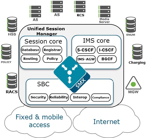
Unified Session Manager
![Diagram of USM as providing edge security for IMS networks.]()
The Unified Session Manager (USM) provides edge security for an IMS network, and should be positioned at access borders to integrate "traditional" SBC functionality with the core IMS session control functions. It provides a user registrar, local subscriber tables and Call Session Control Function components such as Proxy CSCF, Interrogating CSCF, Session CSCF, IMS Access Gateway, Emergency CSCF and Breakout Gateway Control Function.
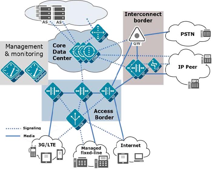
Core Session Manager
![Diagram of CSM as a core network controller between multiple network types in an IMS networks.]()
The Core Session Manager, which should never be positioned at a network edge, is used as a core session controller between multiple network types. It supports SIP in IMS and non-IMS environments, application servers, media servers, gateways, etc. It can be deployed in a distributed, virtualized model on COTS server hardware. The CSM can be used for session routing, interoperability assurance, CAC, and subscriber database integration through HSS, ENUM, or local subscriber table databases.
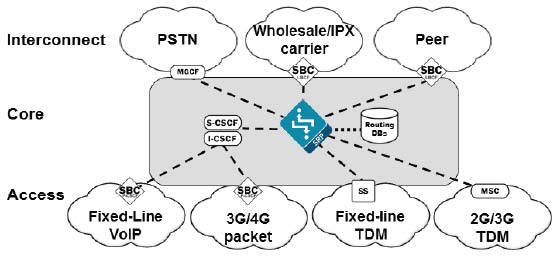
![Diagram of Session Router within a network passing only SIP signaling traffic.]()
The Session Router is a “pure” SIP session router that can be positioned in either a core network or at network borders. When installed at a border, the same SBC protections used in peering and access models can apply. In the network core, the emphasis is on routing and interoperability.
Enterprise Communications Broker
Realm Design Considerations
- A mix of user endpoints, gateways, or peer trunks on the untrusted network
- Varying capabilities or incompatibilities of user agents
- Impacts of blocking traffic to one group of users vs. another (i.e. trust low or medium)
- Service level agreements (SLA) that require Call Admission Controls (CAC)
- Separate endpoints into realms based on trust level (high, medium, low) and that the response to detected abuse is appropriate for them (no action, demotion or blocking)
- Create multiple realms for endpoints based on the type of device – a user endpoint, a gateway, or a peer - since they will have very different considerations for SIP Header Manipulation, trust, signaling thresholds, endpoints behind NAT, and CAC.
- Consider increasing the deny-period from 30 seconds to something longer depending on how much abuse it is believed will be received from a public network and what type of delay users may tolerate.
- Set restricted-latching to sdp so only media received from the IP and port negotiated in signaling will be allowed.
- Pay close attention to the media management settings required for the endpoints and traffic flows (see the mm- parameters on the realm). If one way-audio is experienced this is one place to start investigating.
Original scenario without ClearIP
![Original scenario without ClearIP]()
Key components
- Core Network — The network inside the domain of the telephone service provider.
- Access Network — The network outside the domain of the telephone service provider.
- Call Feature Server — The server of the telephone service provider that provides routing, billing, etc. features.
- SBC Internal Interface — The internal SIP interface configured on the SBC to connect to the Core Network.
- SBC External Interface — The external SIP interface configured on the SBC to connect to the Access Network.
- Network Gateway — The device in the Access Network that sends SIP calls from the telephone service provider.
Routing rules
- CFS-L — Local policies configured on the Call Feature Server.
- SBC-L1 — Local policies configured on the SBC for the SBC Internal Interface/Core Network.
- SBC-L2 — Local policies configured on the SBC for the SBC External Interface/Access Network.
Note: There may be only one set of SBC local policies. We separate it into two sets of policies logically.
Data flow
- F1 — The Call Feature Server sends calls to the SBC Internal Interface based on the local policies CFS-L configured on the Call Feature Server.
- F2 — The SBC Internal Interface forwards the calls to the SBC External Interface based on the local policies SBC-L1 configured on the SBC for the SBC Internal Interface.
- F3 — The SBC External Interface forwards the calls to the Network Gateway based on the local policies SBC-L2 configured on the SBC for the SBC External Interface.
Management Interfaces
The Oracle SBC has two types of interfaces, one for management and the other for signaling and media (otherwise known as services interfaces). Security configuration for each interface is treated separately.
Two management interfaces allow access to the SBC for configuration, monitoring and troubleshooting purposes; a serial (console) interface and an Ethernet interface for remote management (wancom0).
Serial (Console) Interface
As with any industry standard serial interface to a network element, minimal security functions are available. The physical security of the installation location should be assured since console access cannot be blacklisted. However, the Admin Security license (discussed later) does allow for the console port to be disabled.
To avoid unauthorized access to the console interface the console-timeout should be configured to automatically disconnect the console session after an appropriate period of time (i.e. 300 seconds). Timeouts are disabled by default.
If the console port detects a cable disconnect it will also log out any logged in user to prevent unauthorized use.
The console interface should only be connected to a terminal server if the terminal server is deployed in a secure non-public network.
Configuration is detailed in Section 3 “System Configuration” of the ACLI Configuration Guide.
Management Port Configuration
The Wancom0 management interface MUST be connected to and configured on a management network or subnet separate from the service interfaces. If it is not, the SBC is subject to ARP overlap issues, and loss of system access when the network is down or under DDoS attack. Oracle does not support SBC configurations with management and media and service interfaces on the same subnet.
Configuration is detailed in Section 2 “Getting Started” and Section 3 “System Configuration” of the ACLI Configuration Guide.
The SBC provides two levels of user accounts through the Acme Packet Command Line Interface (ACLI): User and Superuser (the “user” and “admin” accounts). SBC no longer supports default passwords and requires these to be changed on first login.
Alternatively, the SBC supports the management of passwords via external RADIUS and TACACS+ servers for finer grain access control. The SBC supports communications with up to six RADIUS servers for this function. At least two entries should be configured to prevent service interruption.
The SBC encrypts sensitive configuration data in the configuration file using a Protected Configuration Password (PCP). This administratively configured password provides security and convenience when migrating configurations to different SBCs. All user passwords should be changed; however, it is especially important to change the PCP (“config” user password) so passwords and keys stored in the config file are secure. TLS, IPsec, and HDR features are protected by the PCP:
CAUTION: Once the PCP password is changed the sensitive information (certificates, IPSec shared secrets, etc) in your configuration file will be re-encrypted using the new PCP the new encryption “salt.”. As a result, previously backed up configuration files cannot be restored unless the password is restored to the value that configuration file was encrypted with.
Configuration is detailed in Section 2 “Getting Started” of the ACLI Configuration Guide, and Section 4 “System Management” of the Maintenance and Troubleshooting Guide in the subsection entitled “Setting a Protected Configuration Password: Matching Configurations.”
The SBC provides a backup user for HDR file synchronization that must be changed. The backup user password can be set using the command “secret backup”. The “secret” command is detailed in Section 3 of the ACLI Reference Guide.
The SBC provides one user for administration of legal intercept functions when a Lawful Intercept (“LI”) license is installed – li-admin. The first time lawful interception is configured you will be prompted to change the password. However if you have installed the license, but never configured lawful interception, the default password may be active and usable via SSH. Procedures to change the password are detailed in the LI Documentation Set.
Boot parameters specify what information the system uses at boot time when it prepares to run applications. The boot parameters allow definition of an IP on the management interface, set the system prompt, and determine the software load that will be used. In addition, there is a boot flag setting that may modify the file location to be used, but may also enable additional features. Administrator access to the command line interface is required to modify the bootflags.
There is seldom a reason to change the boot flag from its default value (0x08). Changes to the boot flags are usually only needed for hardware testing or recovery, debugging, etc.
- 0x01 – Turns off the hardened interface protection on the media interfaces, allowing all ingress traffic
- 0x10 – Enables a second sshd server that provides access to the linux system console. This server process is different from the ssh server used to access the ACLI for configuration.
- 0x80008 – enable source routing on the management port
For further information on boot flags refer to “Configuration Elements A-M” of the ACLI Reference Guide.
The Wancom0 Ethernet management interface should always be deployed in a secure non-public network.
The SBC provides static System Access Control List functionality (ACL) to protect the Wancom0 interface from other devices that can access the management LAN remotely. Only the management station(s) authorized for SBC access such as the Oracle Communications Session Element Manager should be permitted with ACLs. All system ACLs are considered “allow” ACLs, and include a specific IP source address / netmask and the IP protocol allowed. As the first ACL is created an implicit deny rule is inserted as the final ACL.
The “system-access-list” configuration is detailed in Section 3 “System Configuration” of the ACLI Configuration Guide.
Telnet has been removed and only SSH is supported starting 8.0 release.
To avoid unauthorized access to the SSH interface, a timeout should be configured to automatically disconnect the terminal session after an appropriate period of time (i.e. 300 seconds). Timeouts are disabled by default.
The SBC supports viewing, importing, and deleting public ssh keys used for authentication of SSHv2 sessions.
You can select the algorithms which the Oracle Communications Session Border Controller offers during SSH session negotiation.
- ssh-config, encr-algorithms, do not use any *-cbc cipher
- hash-algorithm = hmac-sha2-s56
- host-key = ssh-rsa
- keyex-algorithms = diffie-hellman-group-exchange-sha256
Configuration is detailed in “Getting Started” of the ACLI Configuration Guide, and “System Management” of the Maintenance and Troubleshooting Guide.
Only SFTP is supported.
The SBC can be managed by the Oracle Communications Session Element Manager via ACP through the management interface over TCP ports 3000 and 3001.
By default these ports are enabled in system-config > remote-control. If the SBCs are not remotely controlled by a Session Element Manager then this feature should be disabled.
Oracle recommends protecting ACP communication is recommended to be protected by with TLS. Enable ACP over TLS by configuring acp-tls-profile in system-config.
CAUTION: Disabling the remote-control feature is incompatible with the SBC HA architecture. Hence this functionality is considered optional and should only be deployed where HA and EMS are not used. If the SBCs are deployed in HA configuration, then the remote-control parameter needs to be enabled for the acquire-config feature to function properly.
Configuration is detailed in “System Configuration” of the ACLI Configuration Guide.
Depending on the release, a web based management interface may be accessible via the management network connected to wancom0. The web interface is disabled and not supported for Service Provider SBCs, but Enterprise SBCs include a full featured management and provisioning system.
By default the web interface is disabled. It can be accessed via the wancom0 IP address when enabled. Note that even if the web interface is disabled that the SBC will respond on port 80 by default. However, all new connection requests are immediately torn down with a TCP RST since there is no web server process running, and no kernel rule to forward the request to the web server.
- TLS_DHE_RSA_WITH_AES_256_GCM_SHA384
- TLS_DHE_RSA_WITH_AES_128_GCM_SHA256
- TLS_DHE_RSA_WITH_AES_256_SHA256
- TLS_DHE_RSA_WITH_AES_128_SHA256
- TLS_DHE_RSA_WITH_AES_256_CBC_SHA
- TLS_RSA_WITH_AES_256_CBC_SHA
Note that the DHE ciphers provide perfect forward secrecy, which prevents the session from being decrypted later even if the private key is discovered. Following is an example of system->web-server-config:
Configuration is detailed in Section 2 “Getting Started” of the ACLI Configuration Guide.
Required ClearIP configuration
For ClearIP to return the P-Asserted-Identity with CNAM or the Identity header in the Contact URI of the SIP 302 response, you must ensure the following configurations are in place.
- For embedded Identity header:
- In the Authentication Policies page, there must be an enabled policy configured with the Method field set to In-Band or In-Band and Out-of-Band.
- In the SBCs page, the SBC must be configured with the Identity Header field set to Identity Embedded in Contact URI.
- For [V] modified CNAM on verified calls - In the Verification Policies page, there must be an enabled policy configured with the Indication Method to CNAM or Verstat and CNAM.
- For CNAM lookup - In the CNAM Policies page, there must be an enabled policy configured.
- In the SBCs page, the SBC must be configured with the CNAM Header field set to P-Asserted-Identity Embedded in Contact URI.
4. Outbound call scenarios
After an outbound call has been processed by ClearIP, ClearIP responds in one of three ways:
- No fraud detected
- Fraud detected
- Diverted
These call flows are described below.
Oracle SBC Embedded Header Configuration
Oracle SBC supports embedded header on the session agent level. This should be configured for the SIP Redirect Server session agent.
- redirect-action must be set to recurse.
- request-uri-headers must be set to include all embedded headers that will be passed to outbound INVITE to the called party. In the above example, P-Asserted-Identity header for CNAM and Identity header for STIR/SHAKEN are configured for embedded headers.
Limitations of using embedded headers with routing
In general, the method described for implementing embedded headers is recommended when using the CNAM or Identity header provided by a SIP 302 response from ClearIP because it allows the Oracle SBC configuration to be simpler.
Embedded headers with only the P-Asserted-Identity header with CNAM and not including the Identity header work well even with multiple routing destinations because the additional size of the headers is small.
However, there are some limitations to using embedded headers for the Identity header when ClearIP is simultaneously used to return multiple routing destinations in the SIP 302 Contact header such as for least cost routing (LCR). In these cases, the SIP message becomes too large for the UDP or TCP packet:
- For UDP transport between the Oracle SBC and ClearIP, the SIP 302 can only have one routing destination with the embedded Identity header.
- For TCP transport between the Oracle SBC and ClearIP, the SIP 302 can have at most four routing destinations with the embedded Identity header. Having more than four routing destinations with the embedded Identity header can cause the call to fail.
If you would like to receive the Identity header from ClearIP along with multiple destinations for least cost routing, you cannot use the embedded header approach. You must use a separate approach to add a header manipulation rule (HMR) to copy the standard, non-embedded Identity header from the ClearIP SIP 302 response into the outbound SIP Invite to the called party. Using the HMR approach allows the Identity header to be passed in the 3xx response along with up to twelve routing destinations with UDP and TCP.
Embedded header mechanism
The SIP URI in the SIP 302 response from ClearIP may contain embedded headers. For example, in the following SIP URI, the part highlighted in yellow is an embedded header.
The mechanism described in this document can be used to pass embedded SIP headers within the SIP 302 into the outbound SIP INVITE.
Instructions
A. Configure the AccessRealm SIP interface to use TCP
Important configuration items:
1. transport-protocol TCP 2. trans-expire 5 ClearIP only supports TCP and TLS, so the SIP interface must be configured to support TCP. Trans-expire should be configured to allow the SBC to quickly fail a call attempt. This is useful if ClearIP is unavailable and the SBC timeout for establishing TCP connection is long.
Important configuration items:
ClearIP’s FQDN (Fully Qualified Domain Name), port, and transport protocol must be configured. The redirect action must be configured as recurse to allow the SBC to handle SIP redirect messages directly. Ping options should be configured to allow the SBC to detect ClearIP status instead of waiting for a TCP connection issue timeout.
D. Set the ClearIP session agent as the first enabled destination in the existing local policy
Realm configuration
The SBC is configured with two realms, CoreRealm and AccessRealm. They are mapped to the Core Network and Access Network, respectively. The Core Network includes trusted devices of the telephone service provider. The Access Network includes the devices outside the trusted network, customer devices, and provider devices.
Note: ClearIP can be treated as a trusted device in the Core Network or as a normal device in the Access Network. For the outbound scenario, ClearIP is treated as a device in the Access Network. You can either create a new realm or use an existing realm for ClearIP.
Fraud detected
- The CFS sends a call to the SBC core realm (a)
- The SBC forwards the call to ClearIP (b, c)
- ClearIP returns a SIP 603 (d)
- The SBC drops the call (e, f)
Network diagram and call scenario
- The calling party sends a call to Oracle SBC.
- Oracle SBC forwards the call to ClearIP for services, such as LCR, STIR/SHAKEN, CNAM, etc.
- ClearIP responds with a SIP 302 that includes headers embedded in the Contact header URI, such as STIR/SHAKEN Identity, P-Asserted-Identity with CNAM, etc.
- Oracle SBC copies the embedded headers into the SIP INVITE sent to the called party.
Network interface configuration
Important configuration items:
1. dns-ip-primary 8.8.8.8 2. dns-ip-backup1 8.8.4.4 In the sample configuration below, Google is used as the DNS service provider. Google Public DNS IPv4 servers are configured on the external network interface, M11, which connects to the Access Network. Other DNS servers can be used too. For example, an internal DNS server of the telephone service provider in the Core Network can be configured on the internal network interface, M10, which connects to the Core Network. The desired DNS server IP addresses should be configured.
A previously existing network interface should be configured as shown below.
Highlighted items should be different from the default values. Non-highlighted values can be left as the SBC default values. Some highlighted values such as the name, ip-address, etc. should be left as the previously existing values.
Sample SIP Messages
2. Basic configuration
This section provides the basic standard configuration for an SBC.
![Network diagram]()
Diverted
- The CFS sends a call to the SBC core realm (a)
- The SBC forwards the call to ClearIP (b, c)
- ClearIP returns a SIP 302 with the destination of the diversion device (d)
- SBC tries to forward the call to the diversion device (e)
Читайте также: