
Cisco 3750 настройка voip
The documentation set for this product strives to use bias-free language. For the purposes of this documentation set, bias-free is defined as language that does not imply discrimination based on age, disability, gender, racial identity, ethnic identity, sexual orientation, socioeconomic status, and intersectionality. Exceptions may be present in the documentation due to language that is hardcoded in the user interfaces of the product software, language used based on RFP documentation, or language that is used by a referenced third-party product. Learn more about how Cisco is using Inclusive Language.
Configuring Voice VLAN
These sections contain this configuration information:
Understanding V oice VLAN
The voice VLAN feature enables access ports to carry IP voice traffic from an IP phone. When the switch is connected to a Cisco 7960 IP Phone, the phone sends voice traffic with Layer 3 IP precedence and Layer 2 class of service (CoS) values, which are both set to 5 by default. Because the sound quality of an IP phone call can deteriorate if the data is unevenly sent, the switch supports quality of service (QoS) based on IEEE 802.1p CoS. QoS uses classification and scheduling to send network traffic from the switch in a predictable manner. For more information on QoS, see Chapter37, “Configuring QoS”
The Cisco 7960 IP Phone is a configurable device, and you can configure it to forward traffic with an IEEE 802.1p priority. You can configure the switch to trust or override the traffic priority assigned by a Cisco IP Phone.
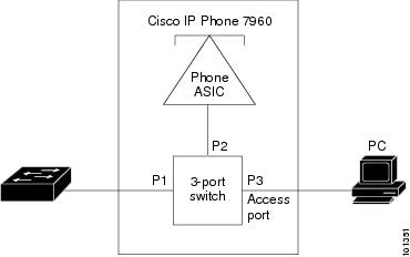
The Cisco IP Phone contains an integrated three-port 10/100 switch as shown in Figure 16-1. The ports provide dedicated connections to these devices:
- Port 1 connects to the switch or other voice-over-IP (VoIP) device.
- Port 2 is an internal 10/100 interface that carries the IP Phone traffic.
- Port 3 (access port) connects to a PC or other device.
Figure 16-1 shows one way to connect a Cisco 7960 IP Phone.
Figure 16-1 Cisco 7960 IP Phone Connected to a Switch
Voice VLAN Configuration Guidelines
These are the voice VLAN configuration guidelines:
- Voice VLAN configuration is only supported on switch access ports; voice VLAN configuration is not supported on trunk ports.You can configure a voice VLAN only on Layer 2 ports.
Note Trunk ports can carry any number of voice VLANs, similar to regular VLANs. The configuration of voice VLANs is not required on trunk ports.
- The voice VLAN should be present and active on the switch for the IP phone to correctly communicate on the voice VLAN. Use the show vlan privileged EXEC command to see if the VLAN is present (listed in the display). If the VLAN is not listed, see “Configuring VLANs,” for information on how to create the voice VLAN.
- Do not configure voice VLAN on private VLAN ports.
- The Power over Ethernet (PoE) switches are capable of automatically providing power to Cisco pre-standard and IEEE 802.3af-compliant powered devices if they are not being powered by an AC power source. For information about PoE interfaces, see the “Configuring a Power Management Mode on a PoE Port” section.
- Before you enable voice VLAN, we recommend that you enable QoS on the switch by entering the mls qos global configuration command and configure the port trust state to trust by entering the mls qos trust cos interface configuration command. If you use the auto-QoS feature, these settings are automatically configured. For more information, see Chapter35, “Configuring QoS”
- You must enable CDP on the switch port connected to the Cisco IP Phone to send the configuration to the phone. (CDP is globally enabled by default on all switch interfaces.)
- The Port Fast feature is automatically enabled when voice VLAN is configured. When you disable voice VLAN, the Port Fast feature is not automatically disabled.
- If the Cisco IP Phone and a device attached to the phone are in the same VLAN, they must be in the same IP subnet. These conditions indicate that they are in the same VLAN:
– They both use IEEE 802.1p or untagged frames.
– The Cisco IP Phone uses IEEE 802.1p frames, and the device uses untagged frames.
– The Cisco IP Phone uses untagged frames, and the device uses IEEE 802.1p frames.
– The Cisco IP Phone uses IEEE 802.1Q frames, and the voice VLAN is the same as the access VLAN.
- The Cisco IP Phone and a device attached to the phone cannot communicate if they are in the same VLAN and subnet but use different frame types because traffic in the same subnet is not routed (routing would eliminate the frame type difference).
- You cannot configure static secure MAC addresses in the voice VLAN.
- Voice VLAN ports can also be these port types:
– IEEE 802.1x authenticated port. See the “Configuring 802.1x Readiness Check” section for more information.
Note If you enable IEEE 802.1x on an access port on which a voice VLAN is configured and to which a Cisco IP Phone is connected, the phone loses connectivity to the switch for up to 30 seconds.
– Protected port. See the “Configuring Protected Ports” section for more information.
– A source or destination port for a SPAN or RSPAN session.
– Secure port. See the “Configuring Port Security” section for more information.
Note When you enable port security on an interface that is also configured with a voice VLAN, you must set the maximum allowed secure addresses on the port to two plus the maximum number of secure addresses allowed on the access VLAN. When the port is connected to a Cisco IP Phone, the phone requires up to two MAC addresses. The phone address is learned on the voice VLAN and might also be learned on the access VLAN. Connecting a PC to the phone requires additional MAC addresses.
Configure the Switch Using a Predefined Macro
In Catalyst 3560, 3750, and 4500 Switches that run Cisco IOS Software Release 12.2 and later, there are few predefined macros available to configure the switch ports. These are examples of macros and their roles in the configuration of switch port to support IP phones:
cisco-phone—This macro is for the switch port where the IP phone is directly connected to it and a PC can be connected to the phone. This macro configures the port with the access VLAN, voice VLAN, port security, spanning-tree portfast/bpduguard, and auto qos voip cisco-phone.
cisco-switch—This macro is for the uplink ports from the access switch to the distribution layer switch. If your voice traffic crosses the switch across the trunk links, you can use the cisco-switch macro in order to configure the uplink port. This macro configures the port with dot1q trunk, spanning-tree link-type point-to-point, and auto qos voip trust. This macro should not be used with the etherchannel/port groups.
Note: These switches support two types of macros:
Smartport macros—This macro is discussed in this section. For more information, refer to Configuring Smartports Macros.
Interface macros—This macro is user-defined and is used to automatically select a range of interfaces for configuration. For more information, refer to Configuring and Using Interface Range Macros.
Issue this show command in order to see the available macro:
Issue this show command in order to view the script of the macro:
This example shows the configuration of switch ports in the IP phone environment:
Chapter: Configuring Voice VLAN
Understanding V oice VLAN
The voice VLAN feature enables access ports to carry IP voice traffic from an IP phone. When the switch is connected to a Cisco 7960 IP Phone, the phone sends voice traffic with Layer 3 IP precedence and Layer 2 class of service (CoS) values, which are both set to 5 by default. Because the sound quality of an IP phone call can deteriorate if the data is unevenly sent, the switch supports quality of service (QoS) based on IEEE 802.1p CoS. QoS uses classification and scheduling to send network traffic from the switch in a predictable manner. For more information on QoS, see Chapter35, “Configuring QoS”
The Cisco 7960 IP Phone is a configurable device, and you can configure it to forward traffic with an IEEE 802.1p priority. You can configure the switch to trust or override the traffic priority assigned by a Cisco IP Phone.
The Cisco IP Phone contains an integrated three-port 10/100 switch as shown in Figure 15-1. The ports provide dedicated connections to these devices:
- Port 1 connects to the switch or other voice-over-IP (VoIP) device.
- Port 2 is an internal 10/100 interface that carries the IP Phone traffic.
- Port 3 (access port) connects to a PC or other device.
Figure 15-1 shows one way to connect a Cisco 7960 IP Phone.
Figure 15-1 Cisco 7960 IP Phone Connected to a Switch
Configuring Voice VLANs
View with Adobe Reader on a variety of devices
Default Voice VLAN Configuration
The voice VLAN feature is disabled by default.
When the voice VLAN feature is enabled, all untagged traffic is sent according to the default CoS priority of the port.
The CoS value is not trusted for IEEE 802.1p or IEEE 802.1Q tagged traffic.
Troubleshoot
Default Voice VLAN Configuration
The voice VLAN feature is disabled by default.
When the voice VLAN feature is enabled, all untagged traffic is sent according to the default CoS priority of the port.
The CoS value is not trusted for IEEE 802.1p or IEEE 802.1Q tagged traffic.
Configure the Switch Port to Carry Both Voice and Data Traffic
When you connect an IP phone to a switch using a trunk link, it can cause high CPU utilization in the switches. As all the VLANs for a particular interface are trunked to the phone, it increases the number of STP instances the switch has to manage. This increases the CPU utilization. Trunking also causes unnecessary broadcast / multicast / unknown unicast traffic to hit the phone link.
In order to avoid this, remove the trunk configuration and keep the voice and access VLAN configured along with Quality of Service (QoS). Technically, it is still a trunk, but it is called a Multi-VLAN Access Port (MVAP). Because voice and data traffic can travel through the same port, you should specify a different VLAN for each type of traffic. You can configure a switch port to forward voice and data traffic on different VLANs. Configure IP phone ports with a voice VLAN configuration. This configuration creates a pseudo trunk, but does not require you to manually prune the unnecessary VLANs.
The voice VLAN feature enables access ports to carry IP voice traffic from an IP phone. The voice VLAN feature is disabled by default. The Port Fast feature is automatically enabled when voice VLAN is configured. When you disable voice VLAN, the Port Fast feature is not automatically disabled. These are the options in the voice VLAN configuration:
Enter a voice VLAN ID in order to send CDP packets that configure the IP phone to transmit voice traffic in 802.1Q frames, tagged with the voice VLAN ID and a Layer 2 CoS value (the default is 5 for voice traffic and 3 for voice control traffic). Valid VLAN IDs are from 1 to 4094. The switch puts the 802.1Q voice traffic into the voice VLAN.
Enter the dot1p keyword in order to send CDP packets that configure the IP phone to transmit voice traffic in 802.1p frames, tagged with VLAN ID 0 and a Layer 2 CoS value (the default is 5 for voice traffic and 3 for voice control traffic). The switch puts the 802.1p voice traffic into the access VLAN.
Enter the untagged keyword in order to send CDP packets that configure the IP phone to transmit untagged voice traffic. The switch puts the untagged voice traffic into the access VLAN.
Enter the none keyword in order to allow the IP phone to use its own configuration and transmit untagged voice traffic. The switch puts the untagged voice traffic into the access VLAN.
This example details that VLAN 10 carries data traffic, and VLAN 20 carries voice traffic:
Note: You cannot disable the PC port span feature in 7960/40 phones.
Настройка механизма обеспечения качества обслуживания
Для упрощения распространения существующих функций обеспечения качества обслуживания можно использовать функцию auto-QoS. Функция Auto-QoS делает предположения о структуре сети. В результате коммутатор может присвоить приоритеты разным потокам данных и правильно использовать выходную очередь, а не использовать механизм обеспечения качества обслуживания по умолчанию. По умолчанию механизм обеспечения качества обслуживания отключен. После этого коммутатор предлагает наилучшее обслуживание каждого пакета вне зависимости от его содержания или размера и отправляет все пакеты из единой очереди.
Функция Auto-QoS настраивает классификацию обеспечения качества обслуживания и выходную очередь. До настройки функции auto-QoS убедитесь, что на коммутаторе не настроен иной механизм обеспечения качества обслуживания. При первой настройке auto-QoS на коммутаторе происходит подключение отключенного механизма обеспечения качества обслуживания, а также настройка очередей и пороговых значений в глобальной конфигурации. Наконец, выполняется настройка порта коммутатора таким образом, чтобы он доверял входящим параметрам обеспечения качества обслуживания, а также настройка параметров формирования трафика для этого порта. После этого при каждой следующей настройке любого порта с использованием функции auto-QoS выполняется только настройка параметров обеспечения качества обслуживания для портов коммутатора.
Выполните команду debug auto qos в режиме включения (режим enable) и настройте auto-qos для портов коммутатора, чтобы выяснить какая конфигурация обеспечения качества обслуживания была применена при настройке auto-QoS. Команда отладки auto qos выводит список команд коммутатора.
После выполнения команды auto qos можно изменить конфигурацию обеспечения качества обслуживания в соответствии со своими требованиями. Однако это делать не рекомендуется. Ниже можно увидеть список доступных параметров команды auto qos voice:
Настройка Auto-QoS для коммутаторов Catalyst, на которых установлено ПО IOS
Хотя синтакисис команды auto qos одинаков на всех коммутаторах Catalyst, настройки обеспечения качества обслуживания, применяемые на разных коммутаторах Catalyst при помощи функции auto-QoS, различаются для разных коммутаторов.
Настройка механизма обеспечения качества обслуживания в каскадном подключении уровня 2
Если речевой трафик будет проходить через коммутатор по магистральной сети, необходимо настроить параметры обеспечения качества обслуживания для магистральных портов. В этом случае необходимо использовать команду auto qos voip trust вместо команды auto qos voip cisco-phone.
Настройка Auto-QoS для магистральных линий коммутаторов Catalyst, на которых установлено ПО IOS
Настройка механизма обеспечения качества обслуживания в каскадном подключении уровня 3
Настройка Auto-QoS для порта уровня 3 коммутатора Catalyst, на котором установлено ПО IOS
Requirements
There are no specific requirements for this document.
Verify
Issue this show interface command in order to confirm that the configuration works properly on switches that run Cisco IOS:
The Output Interpreter Tool (registered customers only) (OIT) supports certain show commands. Use the OIT to view an analysis of show command output.
Components Used
This document is not restricted to specific software and hardware versions.
Results
IP Phones Do Not Get IP Address From DHCP Server
If Dynamic Address Resolution Protocol (ARP) Inspection (DAI) is enabled in the switch, it depends on the entries in the DHCP snooping binding database to verify IP-to-MAC address bindings in incoming ARP requests and ARP responses. Make sure to enable DHCP snooping in order to permit ARP packets that have dynamically assigned IP addresses.
Also, the ARP Access Control Lists (ACLs) take precedence over entries in the DHCP snooping binding database. The switch uses ACLs only if you configure them by using the ip arp inspection filter vlan global configuration command. The switch first compares ARP packets to user-configured ARP ACLs. If the ARP ACL denies the ARP packet, the switch also denies the packet even if a valid binding exists in the database populated by DHCP snooping.
Настройка коммутатора с использованием предварительно заданного макроса
Для коммутаторов Catalyst 3560, 3750 и 4500, использующих программное обеспечение Cisco IOS версии 12.2 и выше, доступно несколько предварительно заданных макросов для настройки портов коммутатора. Ниже приведены примеры макросов и их роль в настройке порта коммутатора для поддержки IP-телефонов.
cisco-switch — Этот макрос предназначен для каскадного соединения портов от коммутатора доступа до коммутатора уровня распределения. Если речевой трафик проходит через коммутатор по магистральным линиям, можно использовать макрос cisco-switch для настройки каскадного соединения портов. Этот макрос позволяет настроить порт с транком dot1q, двухточечным соединением по протоколу связующего дерево и auto qos voip trust. Этот макрос не следует использовать для групп etherchannel/port.
Используйте команду show для просмотра доступных макросов:
Используйте команду show для просмотра сценария макроса:
В этом примере показана конфигурация портов коммутатора в окружении IP-телефона:
Настройка коммутатора с использованием предварительно заданного макроса
Configuring Voice VLAN
These sections contain this configuration information:
Configuring the Priority of Incoming Data Frames
You can connect a PC or other data device to a Cisco IP Phone port. To process tagged data traffic (in IEEE 802.1Q or IEEE 802.1p frames), you can configure the switch to send CDP packets to instruct the phone how to send data packets from the device attached to the access port on the Cisco IP Phone. The PC can generate packets with an assigned CoS value. You can configure the phone to not change (trust) or to override (not trust) the priority of frames arriving on the phone port from connected devices.
Beginning in privileged EXEC mode, follow these steps to set the priority of data traffic received from the nonvoice port on the Cisco IP Phone:
configure terminal
Enter global configuration mode.
interface interface-id
Specify the interface connected to the Cisco IP Phone, and enter interface configuration mode.
switchport priority extend
< cos value | trust >
Set the priority of data traffic received from the Cisco IP Phone access port:
- cosvalue —Configure the phone to override the priority received from the PC or the attached device with the specified CoS value. The value is a number from 0 to 7, with 7 as the highest priority. The default priority is cos 0.
- trust —Configure the phone access port to trust the priority received from the PC or the attached device.
Return to privileged EXEC mode.
show interfaces interface-id switchport
Verify your entries.
copy running-config startup-config
(Optional) Save your entries in the configuration file.
This example shows how to configure a port connected to a Cisco IP Phone to not change the priority of frames received from the PC or the attached device:
To return the port to its default setting, use the no switchport priority extend interface configuration command.
Introduction
This document provides sample configurations on Catalyst switches in order to connect to Cisco IP phones. This document includes the switch port, power inline, and quality of service (QoS) configurations. The switch port configuration uses a predefined macro which configures the switch port and QoS settings with minimum commands.
C onfiguring a Port Connected to a Cisco 7960 IP Phone
Because a Cisco 7960 IP Phone also supports a connection to a PC or other device, a port connecting the switch to a Cisco IP Phone can carry mixed traffic. You can configure a port to decide how the Cisco IP Phone carries voice traffic and data traffic.
These sections contain this configuration information:
Cisco IP Phone Voice Traffic
You can configure an access port with an attached Cisco IP Phone to use one VLAN for voice traffic and another VLAN for data traffic from a device attached to the phone. You can configure access ports on the switch to send Cisco Discovery Protocol (CDP) packets that instruct an attached phone to send voice traffic to the switch in any of these ways:
- In the voice VLAN tagged with a Layer 2 CoS priority value
- In the access VLAN tagged with a Layer 2 CoS priority value
- In the access VLAN, untagged (no Layer 2 CoS priority value)
Note In all configurations, the voice traffic carries a Layer 3 IP precedence value (the default is 5 for voice traffic and 3 for voice control traffic).
Chapter: Configuring Voice VLANs
C onfiguring a Port Connected to a Cisco 7960 IP Phone
Because a Cisco 7960 IP Phone also supports a connection to a PC or other device, a port connecting the switch to a Cisco IP Phone can carry mixed traffic. You can configure a port to decide how the Cisco IP Phone carries voice traffic and data traffic.
These sections contain this configuration information:
Устранение неполадок
Условные обозначения
См. дополнительные сведения об условных обозначениях в документе Технические советы Cisco. Условные обозначения.
Displaying Voice VLAN
To display voice VLAN configuration for an interface, use the show interfaces interface-id switchport privileged EXEC command.
В этом документе приведены примеры конфигурации коммутаторов Catalyst для подсоединения IP-телефонов Cisco. В этом документе содержится конфигурация порта коммутатора, встроенного источника питания и механизма обеспечения качества обслуживания (QoS). Конфигурация порта коммутатора выполняется предварительно заданным макросом, который настраивает порт коммутатора и механизм обеспечения качества обслуживания с использованием минимального числа команд.
Configurations
The configuration of the Catalyst switch contains these configurations:
Catalyst 3560G: No Power to IP Phone After the Non-PoE Device is Unplugged
The Catalyst 3560G does not provide inline power to an IP phone connected to a port where a non-powered device was previously connected and unplugged from the port. This problem occurs with PoE settings of both auto and static on the port. This issue can also occur in 3750 Series Switches. It has been identified in Cisco bug ID CSCsc10999 (registered customers only) .
The workaround is to issue shutdown/no shutdown on the port. Then, the switch provides power to the IP phone. This issue has been resolved in Cisco IOS Software Release 12.2(25)SED1.
Проверка
Чтобы убедиться, что конфигурация на коммутаторах с ПО Cisco IOS работает правильно, используйте команду show interface:
Book Title
Catalyst 3750-X and 3560-X Switch Software Configuration Guide, Release 12.2(55)SE
Configure
In this section, you are presented with the information to configure the features described in this document.
Note: Use the Command Lookup Tool (registered customers only) to obtain more information on the commands used in this section.
Настройки
Конфигурация коммутатора Catalyst содержит следующие настройки:
Voice VLAN Configuration Guidelines
These are the voice VLAN configuration guidelines:
- Voice VLAN configuration is only supported on switch access ports; voice VLAN configuration is not supported on trunk ports.
Note Trunk ports can carry any number of voice VLANs, similar to regular VLANs. The configuration of voice VLANs is not required on trunk ports.
- The voice VLAN should be present and active on the switch for the IP phone to correctly communicate on the voice VLAN. Use the show vlan privileged EXEC command to see if the VLAN is present (listed in the display). If the VLAN is not listed, see “Configuring VLANs,” for information on how to create the voice VLAN.
- Do not configure voice VLAN on private VLAN ports.
- The Power over Ethernet (PoE) switches are capable of automatically providing power to Cisco pre-standard and IEEE 802.3af-compliant powered devices if they are not being powered by an AC power source. For information about PoE interfaces, see the “Configuring a Power Management Mode on a PoE Port” section.
- Before you enable voice VLAN, we recommend that you enable QoS on the switch by entering the mls qos global configuration command and configure the port trust state to trust by entering the mls qos trust cos interface configuration command. If you use the auto-QoS feature, these settings are automatically configured. For more information, see Chapter37, “Configuring QoS”
- You must enable CDP on the switch port connected to the Cisco IP Phone to send the configuration to the phone. (CDP is globally enabled by default on all switch interfaces.)
- The Port Fast feature is automatically enabled when voice VLAN is configured. When you disable voice VLAN, the Port Fast feature is not automatically disabled.
- If the Cisco IP Phone and a device attached to the phone are in the same VLAN, they must be in the same IP subnet. These conditions indicate that they are in the same VLAN:
– They both use IEEE 802.1p or untagged frames.
– The Cisco IP Phone uses IEEE 802.1p frames, and the device uses untagged frames.
– The Cisco IP Phone uses untagged frames, and the device uses IEEE 802.1p frames.
– The Cisco IP Phone uses IEEE 802.1Q frames, and the voice VLAN is the same as the access VLAN.
- The Cisco IP Phone and a device attached to the phone cannot communicate if they are in the same VLAN and subnet but use different frame types because traffic in the same subnet is not routed (routing would eliminate the frame type difference).
- You cannot configure static secure MAC addresses in the voice VLAN.
- Voice VLAN ports can also be these port types:
– IEEE 802.1x authenticated port. See the “Configuring 802.1x Readiness Check” section for more information.
Note If you enable IEEE 802.1x on an access port on which a voice VLAN is configured and to which a Cisco IP Phone is connected, the phone loses connectivity to the switch for up to 30 seconds.
– Protected port. See the “Configuring Protected Ports” section for more information.
– A source or destination port for a SPAN or RSPAN session.
– Secure port. See the “Configuring Port Security” section for more information.
Note When you enable port security on an interface that is also configured with a voice VLAN, you must set the maximum allowed secure addresses on the port to two plus the maximum number of secure addresses allowed on the access VLAN. When the port is connected to a Cisco IP Phone, the phone requires up to two MAC addresses. The phone address is learned on the voice VLAN and might also be learned on the access VLAN. Connecting a PC to the phone requires additional MAC addresses.
Displaying Voice VLAN
To display voice VLAN configuration for an interface, use the show interfaces interface-id switchport privileged EXEC command.
The documentation set for this product strives to use bias-free language. For the purposes of this documentation set, bias-free is defined as language that does not imply discrimination based on age, disability, gender, racial identity, ethnic identity, sexual orientation, socioeconomic status, and intersectionality. Exceptions may be present in the documentation due to language that is hardcoded in the user interfaces of the product software, language used based on RFP documentation, or language that is used by a referenced third-party product. Learn more about how Cisco is using Inclusive Language.
Настройка
В этом разделе приводятся сведения о настройке функций, описанных в данном документе.
The 7935 IP Conference Phone Receives Data IP Address Instead of Voice IP Address
If the 7935 IP Conference Phone is connected to a switch, the conference phone receives the IP address from the data VLAN. If the 7960 IP Phone is connected on the same switch port as the 7935 IP Conference Phone, the 7960 receives the IP address on the voice VLAN.
This issue is due to the design of the 7935 IP Conference Phones. This conference phone does not have a 10/100 port to connect a PC like other 7900 Series IP Phones have. The concept of voice VLAN or auxiliary VLAN does not directly apply to the 7935 IP Conference Phones.
Refer to 7935 IP Conference Phone Optimal Performance Configuration for the detailed explanation and the solution.
Требования
Для данного документа нет особых требований.
Configuring Voice VLAN
This chapter describes how to configure the voice VLAN feature on the Catalyst 3750-X or 3560-X switch. Unless otherwise noted, the term switch refers to a Catalyst 3750-X or 3560-X standalone switch and to a Catalyst 3750-X switch stack. Voice VLAN is referred to as an auxiliary VLAN in some Catalyst 6500 family switch documentation.
Note For complete syntax and usage information for the commands used in this chapter, see the command reference for this release.
This chapter consists of these sections:
Cisco IP Phone Data Traffic
The switch can also process tagged data traffic (traffic in IEEE 802.1Q or IEEE 802.1p frame types) from the device attached to the access port on the Cisco IP Phone (see Figure 15-1). You can configure Layer 2 access ports on the switch to send CDP packets that instruct the attached phone to configure the phone access port in one of these modes:
- In trusted mode, all traffic received through the access port on the Cisco IP Phone passes through the phone unchanged.
- In untrusted mode, all traffic in IEEE 802.1Q or IEEE 802.1p frames received through the access port on the Cisco IP Phone receive a configured Layer 2 CoS value. The default Layer 2 CoS value is 0. Untrusted mode is the default.
Note Untagged traffic from the device attached to the Cisco IP Phone passes through the phone unchanged, regardless of the trust state of the access port on the phone.
Configure QoS
You can use the auto-QoS feature to simplify the deployment of QoS features that exist. Auto-QoS makes assumptions about the network design. As a result, the switch can prioritize different traffic flows and appropriately use the egress queues instead of using the default QoS behavior. The default is that QoS is disabled. Then, the switch offers best-effort service to each packet, regardless of the packet content or size, and sends it from a single queue.
Auto-QoS configures QoS classification and configures egress queues. Before you configure auto-QoS, make sure you do not have any QoS configured on the switch. When you configure auto-QoS for the first time on the switch, QoS is enabled on the switch if it is disabled, and configures queues and thresholds in the global configuration. Finally, it configures the switch port to trust the incoming CoS parameters and configures the traffic-shaping parameters for that port. After this, every time you configure any port with auto-QoS, it only configures the switch port with QoS parameters.
Enable the debug auto qos command in the enable mode and configure the auto-qos on the switch port in order to find out what QoS configurations are applied during auto-QoS configuration. The debug auto qos shows the commands that are applied on the switch.
Although the auto qos command syntax is same on all the Catalyst switches, the QoS configurations, which are applied on the Catalyst switches by auto-QoS, are different amongst the Catalyst switches.
Configure QoS on the Layer 2 Uplink
If the voice traffic is going to cross the switch via the trunk links, you need to configure the QoS parameters on the trunk ports. In this case, you need to issue the auto qos voip trust command instead of the auto qos voip cisco-phone command.
Configure QoS on the Layer 3 Uplink
If the voice traffic crosses the Layer 3 link, you need to configure the port with the auto qos voip trust command and you need to configure the port to trust dscp. This example shows the configuration of the Layer 3 port to carry voice traffic:
Configuring Voice VLAN
This chapter describes how to configure the voice VLAN feature on the Catalyst 3750 switch. Unless otherwise noted, the term switch refers to a standalone switch and a switch stack. Voice VLAN is referred to as an auxiliary VLAN in some Catalyst 6500 family switch documentation.
Note For complete syntax and usage information for the commands used in this chapter, see the command reference for this release.
This chapter consists of these sections:
Catalyst 3560G: на IP-телефон не подается питание после отсоединения устройства с питанием не через Ethernet
Обходным путем эту проблему можно решить при помощи команды shutdown/no shutdown для данного порта. После этого коммутатор начинает подавать питание на IP-телефон. Эта проблема была устранена в программном обеспечении Cisco IOS, выпуск 12.2(25)SED1.
Cisco IP Phone Data Traffic
The switch can also process tagged data traffic (traffic in IEEE 802.1Q or IEEE 802.1p frame types) from the device attached to the access port on the Cisco IP Phone (see Figure 16-1). You can configure Layer 2 access ports on the switch to send CDP packets that instruct the attached phone to configure the phone access port in one of these modes:
- In trusted mode, all traffic received through the access port on the Cisco IP Phone passes through the phone unchanged.
- In untrusted mode, all traffic in IEEE 802.1Q or IEEE 802.1p frames received through the access port on the Cisco IP Phone receive a configured Layer 2 CoS value. The default Layer 2 CoS value is 0. Untrusted mode is the default.
Note Untagged traffic from the device attached to the Cisco IP Phone passes through the phone unchanged, regardless of the trust state of the access port on the phone.
Conventions
Refer to Cisco Technical Tips Conventions for more information on document conventions.
Background Information
This document explains the configuration of the switches that connect the PCs and IP phones on a switch port. The Cisco IP phone contains an integrated three-port 10/100 switch. The ports are dedicated connections.
Port 1 connects to the Catalyst switch or other device that supports voice-over-IP.
Port 2 is an internal 10/100 interface that carries the phone traffic.
Port 3 connects to a PC or other device.
Note: Only two ports are physically viewable. The other port is an internal port and is not physically viewable. In this section, port 2 is not viewable.
The switch has two VLANs: one carries data traffic and one carries voice traffic. The switch port can be either access VLAN or trunk VLAN, but you need to configure a voice VLAN to carry the voice traffic.
If your switch has a module that can provide Power over Ethernet (PoE) to end stations, you can set each interface on the module to automatically detect and apply PoE if the end station requires power. By default, when the switch detects a powered device on an interface, it assumes that the powered device consumes the maximum port it can provide. The maximum is 7 W on a legacy PoE module and 15.4W on the IEEE PoE modules introduced in Cisco IOS® Software Release 12.2(18)EW. When the switch receives a Cisco Discovery Protocol (CDP) packet from the powered device, the wattage automatically adjusts downward to the specific amount required by that device. Normally, this automatic adjustment works well, and no further configuration is required or recommended. However, you can specify the consumption of the powered device for the entire switch (or for a particular interface) to provide extra functionality from your switch. This is useful when CDP is disabled or not available.
Because the sound quality of an IP phone call can deteriorate if the data is sent unevenly, the switch uses QoS-based on IEEE 802.1p class of service (CoS). QoS uses classification and scheduling to transmit network traffic from the switch in a predictable manner. Refer to Configuring QoS for more information on QoS. Cisco AutoQoS automates consistent deployment of QoS features across Cisco routers and switches. It enables various Cisco QoS components based on the network environment and Cisco best-practice recommendations.
Con figuring Cisco IP Phone Voice Traffic
You can configure a port connected to the Cisco IP Phone to send CDP packets to the phone to configure the way in which the phone sends voice traffic. The phone can carry voice traffic in IEEE 802.1Q frames for a specified voice VLAN with a Layer 2 CoS value. It can use IEEE 802.1p priority tagging to give voice traffic a higher priority and forward all voice traffic through the native (access) VLAN. The Cisco IP Phone can also send untagged voice traffic or use its own configuration to send voice traffic in the access VLAN. In all configurations, the voice traffic carries a Layer 3 IP precedence value (the default is 5).
Beginning in privileged EXEC mode, follow these steps to configure voice traffic on a port:
configure terminal
Enter global configuration mode.
interface interface-id
Specify the interface connected to the phone, and enter interface configuration mode.
mls qos trust cos
Configure the interface to classify incoming traffic packets by using the packet CoS value. For untagged packets, the port default CoS value is used.
Note Before configuring the port trust state, you must first globally enable QoS by using the mls qos global configuration command.
Configure how the Cisco IP Phone carries voice traffic:
- detect —Configure the interface to detect and recognize a Cisco IP phone.
- cisco-phone —When you initially implement the switchport voice detect command, this is the only allowed option. The default is no switchport voice detect cisco-phone [ full-duplex ].
- full-duplex —(Optional) Configure the switch to only accept a full-duplex Cisco IP phone.
- vlan-id —Configure the phone to forward all voice traffic through the specified VLAN. By default, the Cisco IP Phone forwards the voice traffic with an IEEE 802.1Q priority of 5. Valid VLAN IDs are 1 to 4094.
- dot1p —By default, the Cisco IP Phone forwards the voice traffic with an IEEE 802.1p priority of 5.
- none —Allow the phone to use its own configuration to send untagged voice traffic.
- untagged —Configure the phone to send untagged voice traffic.
Return to privileged EXEC mode.
show interfaces interface-id switchport or
show running-config interface interface-id
Verify your voice VLAN entries.
Verify your QoS and voice VLAN entries.
copy running-config startup-config
(Optional) Save your entries in the configuration file.
This example shows how to configure a port connected to a Cisco IP Phone to use the CoS value to classify incoming traffic, to use IEEE 802.1p priority tagging for voice traffic, and to use the default native VLAN (VLAN 0) to carry all traffic:
To return the port to its default setting, use the no switchport voice vlan interface configuration command.
This example shows how to enable switchport voice detect on a Cisco IP Phone:
This example shows how to disable switchport voice detect on a Cisco IP Phone:
Настройка порта коммутатора для трафика данных и передачи речевых сигналов
Введите ключевое слово untagged для передачи пакетов CDP для настройки передачи непомеченного речевого трафика от IP-телефона. Коммутатор помещает непомеченный речевой трафик в виртуальную локальную сеть доступа.
Введите ключевое слово none, чтобы IP-телефон мог использовать собственную конфигурацию и передавать непомеченный речевой трафик. Коммутатор помещает непомеченный речевой трафик в виртуальную локальную сеть доступа.
В следующем примере виртуальная локальная сеть VLAN 10 используется для трафика данных, а виртуальная локальная сеть VLAN 20 для голосового трафика.
Конфигурация коммутатора Catalyst для трафика данных и передачи речевых сигналов
Book Title
Catalyst 3750-X and 3560-X Switch Software Configuration Guide, Release 12.2(55)SE
Results
Используемые компоненты
Данный документ не ограничен отдельными версиями программного и аппаратного обеспечения.
IP-телефон для конференц-связи 7935 вместо IP-адреса для передачи голоса получает IP-адрес для передачи данных
The documentation set for this product strives to use bias-free language. For the purposes of this documentation set, bias-free is defined as language that does not imply discrimination based on age, disability, gender, racial identity, ethnic identity, sexual orientation, socioeconomic status, and intersectionality. Exceptions may be present in the documentation due to language that is hardcoded in the user interfaces of the product software, language used based on RFP documentation, or language that is used by a referenced third-party product. Learn more about how Cisco is using Inclusive Language.
IP Phones Do Not Come Up with MAC Authentication Bypass (MAB)
In a switch that uses MAB to grant access to network devices, all IP phone MAC addresses learned through CDP are allowed on the auxiliary (voice) VLAN. However, if the IP phone is alone (without any PC connected to it) and connected to a port configured with both data and voice VLANs, then the IP phone is placed on the data VLAN. Therefore, the IP phone will face issues when it registers with Cisco CallManager.
In order to overcome this issue, either configure the access VLAN of port with the ID of voice VLAN, or connect a PC to the IP phone.
Contents
Network Diagram
This document uses this network setup:
Configure Inline Power Support
Cisco offers a comprehensive range of Catalyst switches that support PoE with 802.3af compliant, which also supports Cisco pre-standard PoE implementation. IEEE 802.3af-2003 describes five power classes that a device can belong to. The default power classification within IEEE 802.3af delivers 15.4W per power device. Delivery of PoE that uses the IEEE 802.3af default classification can significantly increase the power requirements on both the Power Sourcing Equipment (PSE) switch and the power infrastructure. In order to provide PoE in a cost effective and efficient manner, Catalyst switches support intelligent power management in addition to IEEE 802.3af classification. This enables a powered device and PSE to negotiate their respective capabilities in order to explicitly manage how much power is required for the device, and also how the PSE-capable switch manages the allocation of power to individual powered devices.
Issue this show power inline command in order to view the default power consumption a switch can supply:
By default, all the switch ports are configured to automatically detect and power the PoE devices. Issue this show power inline command in order to view the power inline configuration status of any port:
You can issue the power inline command in order to configure the inline power of an individual port. This shows the power inline configuration options:
Auto—By default, PoE-capable ports are configured to auto. The powered devices are powered up on a first-come, first-serve basis. If not enough inline power is available from the power supplies for all the powered devices in auto mode, there is no guarantee which powered devices are powered up.
Static—Static ports have a higher priority than auto ports in terms of power allocation and shutdown. The switch allocates power for a static port when it is configured. Power is then reserved for the port even when nothing is connected. The amount of power allocated can either use the default maximum value (15.4W) or can be specified when this option is used. This allocated amount is never adjusted by IEEE class or by CDP messages.
Never—The supervisor engine does not direct the switching module to power up the port even if a non-powered phone is connected.
With the static mode, the powered device is guaranteed to come online when plugged in. This is typically used for higher-priority users, such as corporate executives or wireless access points. However, if the IEEE class wattage of the powered device is greater than the maximum wattage of the static port, the powered device is not powered up. Similarly, in the case of a Cisco prestandard PoE, if the CDP message from the powered device indicates that the wattage required is greater than the maximum allocated on the static port, the port is powered down. In situations where the number of static ports desired exceeds the capabilities of the power supply, a newly designated static port is placed in an error-disable state, and 0W are allocated. If the switch needs to shut down powered devices because a power supply fails and there is insufficient power, auto-powered devices are shut before static-powered devices.
Настройка встроенного источника питания
Cisco предлагает широкий диапазон коммутаторов Catalyst с поддержкой питания через Ethernet и совместимых с 802.3af, которые также поддерживают предстандартные реализации Cisco для подачи питания через Ethernet. В IEEE 802.3af-2003 описаны пять классов электропитания, которым может соответствовать устройство. В соответствии с классификацией по электропитанию IEEE 802.3af на каждое электрическое устройство подается мощность 15,4 Вт. Подача электропитание через Ethernet с использованием классификации IEEE 802.3af по умолчанию может значительно повысить требования к электропитанию как на переключателе питающего устройства (PSE), так в инфраструктуре электропитания. Для обеспечения рентабельного и эффективного питания через Ethernet коммутаторы Catalyst поддерживают не только классификацию IEEE 802.3af, но и интеллектуальную систему управления питанием. Благодаря этому устройство, потребляющее электропитание, и питающее устройство согласовывают свои мощности и явно регулируют, какую мощность необходимо подать на устройство, а также каким образом переключатель питающего устройства направляет питание на отдельные устройства, потребляющие электропитание.
Введите команду show power inline, чтобы увидеть потребление электроэнергии по умолчанию, которое может подать коммутатор:
По умолчанию все порты коммутатора настроены для автоматического определения устройств с питанием через Ethernet и подачи на них питания. Введите команду show power inline, чтобы увидеть состояние конфигурации встроенного источника питания любого из портов:
Для настройки встроенного источника питания отдельного порта можно использовать команду power inline. Ниже приведены параметры конфигурации встроенного источника питания:
Auto — По умолчанию порт настроен на поддержку питания через Ethernet. Устройства, потребляющие электроэнергию, обслуживаются в порядке поступления запросов. Если в автоматическом режиме встроенные источники питания не подают достаточно электроэнергии для обслуживания всех устройств, потребляющих электроэнергию, то невозможно гарантировать, на какое из них будет подаваться питание.
Never — Управляющий модуль не посылает команду на модуль переключений для подачи питания на порт даже при подключении телефона, на который не подается электропитание.
В следующем примере показана конфигурация встроенного источника питания порта коммутатора. Как объяснялось ранее в этом разделе, по умолчанию в качестве настройки встроенного источника питания порта устанавливается auto. При изменении конфигурации по умолчанию, чтобы вернуть настройку auto, настройте порт следующим образом.
Настройте встроенный источник питания для коммутатора Catalyst, на котором установлено ПО Cisco IOS
Prerequisites
Configuring Voice VLAN
View with Adobe Reader on a variety of devices
Cisco IP Phone Voice Traffic
You can configure an access port with an attached Cisco IP Phone to use one VLAN for voice traffic and another VLAN for data traffic from a device attached to the phone. You can configure access ports on the switch to send Cisco Discovery Protocol (CDP) packets that instruct an attached phone to send voice traffic to the switch in any of these ways:
- In the voice VLAN tagged with a Layer 2 CoS priority value
- In the access VLAN tagged with a Layer 2 CoS priority value
- In the access VLAN, untagged (no Layer 2 CoS priority value)
Note In all configurations, the voice traffic carries a Layer 3 IP precedence value (the default is 5 for voice traffic and 3 for voice control traffic).
Book Title
Catalyst 3750 Software Configuration Guide, Release 12.2(55)SE
Общие сведения
В этом документе объясняется конфигурация коммутаторов, соединяющих ПК и IP-телефоны через порт коммутатора. IP-телефон Cisco содержат интегрированный коммутатор 10/100 с тремя портами. Эти порты выделены для определенных подключений.
Порт 1 служит для подсоединения к коммутатору Catalyst или другому устройству, поддерживающему технологию передачи речи по протоколу IP.
Порт 2 – это внутренний интерфейс 10/100 для передачи трафика, проходящего через телефон.
Порт 3 служит для подсоединения к ПК или другому устройству.
Примечание: Физически можно увидеть только два порта. Третий порт является внутренним, и увидеть его нельзя. В этом разделе порт 2 не виден.
Если в коммутаторе содержится модуль, обеспечивающий конечные станции питанием через Ethernet, то можно настроить каждый интерфейс этого модуля таким образом, чтобы он автоматически определял, что конечной станции необходимо питание и подавал на нее питание через Ethernet. По умолчанию, когда коммутатор определяет в интерфейсе устройство, на которое подается электропитание, он предполагает, что это устройство потребляет максимальную мощность, которая может быть подана через порт. В традиционных модулях максимум мощности питания через Ethernet составляет 7 Вт, а в модулях IEEE PoE, включенных в программное обеспечение Cisco IOS®, выпуск 12.2(18)EW он составляет 15,4 Вт. Когда коммутатор получает пакет данных по протоколу обнаружения Cisco (CDP) от устройства, на которое подается электропитание, потребляемая мощность автоматически уменьшается в соответствии с требованиям конкретного устройства. Обычно эта автоматическая регулировка срабатывает правильно, и после нее дальнейшая регулировка не требуется и не рекомендуется. Однако можно указать потребление электропитания на устройстве для всего коммутатора (или для конкретного интерфейса), чтобы обеспечить на коммутаторе дополнительную функциональность. Это полезно, когда протокол CDP отключен или не доступен.
Поскольку при неравномерной передаче данных качество речерых вызовов на IP-телефоне может снизиться, в коммутаторе используется механизм обеспечения качества обслуживания на базе класса обслуживания IEEE 802.1p. Механизм обеспечения качества обслуживания при передаче сетевого трафика с коммутатора использует классификацию и расписания предсказуемым образом. См. дополнительные сведения по механизму обеспечения качества обслуживания в разделе Настройка QoS. Функция Cisco AutoQoS обеспечивает автоматическое последовательное применение механизма обеспечения качества обслуживания во всех маршрутизаторах и коммутаторах Cisco. Она подключает различные компоненты обеспечения качества обслуживания Cisco в зависимости от сетевого окружения и рекомендаций Cisco.
Configuring the Priority of Incoming Data Frames
You can connect a PC or other data device to a Cisco IP Phone port. To process tagged data traffic (in IEEE 802.1Q or IEEE 802.1p frames), you can configure the switch to send CDP packets to instruct the phone how to send data packets from the device attached to the access port on the Cisco IP Phone. The PC can generate packets with an assigned CoS value. You can configure the phone to not change (trust) or to override (not trust) the priority of frames arriving on the phone port from connected devices.
Beginning in privileged EXEC mode, follow these steps to set the priority of data traffic received from the nonvoice port on the Cisco IP Phone:
configure terminal
Enter global configuration mode.
interface interface-id
Specify the interface connected to the Cisco IP Phone, and enter interface configuration mode.
switchport priority extend
< cos value | trust >
Set the priority of data traffic received from the Cisco IP Phone access port:
- cosvalue —Configure the phone to override the priority received from the PC or the attached device with the specified CoS value. The value is a number from 0 to 7, with 7 as the highest priority. The default priority is cos 0.
- trust —Configure the phone access port to trust the priority received from the PC or the attached device.
Return to privileged EXEC mode.
show interfaces interface-id switchport
Verify your entries.
copy running-config startup-config
(Optional) Save your entries in the configuration file.
This example shows how to configure a port connected to a Cisco IP Phone to not change the priority of frames received from the PC or the attached device:
To return the port to its default setting, use the no switchport priority extend interface configuration command.
Схема сети
В данном документе используется следующая настройка сети:
Предварительные условия
Con figuring Cisco IP Phone Voice Traffic
You can configure a port connected to the Cisco IP Phone to send CDP packets to the phone to configure the way in which the phone sends voice traffic. The phone can carry voice traffic in IEEE 802.1Q frames for a specified voice VLAN with a Layer 2 CoS value. It can use IEEE 802.1p priority tagging to give voice traffic a higher priority and forward all voice traffic through the native (access) VLAN. The Cisco IP Phone can also send untagged voice traffic or use its own configuration to send voice traffic in the access VLAN. In all configurations, the voice traffic carries a Layer 3 IP precedence value (the default is 5).
Beginning in privileged EXEC mode, follow these steps to configure voice traffic on a port:
configure terminal
Enter global configuration mode.
interface interface-id
Specify the interface connected to the phone, and enter interface configuration mode.
mls qos trust cos
Configure the interface to classify incoming traffic packets by using the packet CoS value. For untagged packets, the port default CoS value is used.
Note Before configuring the port trust state, you must first globally enable QoS by using the mls qos global configuration command.
Configure how the Cisco IP Phone carries voice traffic:
- detect —Configure the interface to detect and recognize a Cisco IP phone.
- cisco-phone —When you initially implement the switchport voice detect command, this is the only allowed option. The default is no switchport voice detect cisco-phone [ full-duplex ] .
- full-duplex —(Optional) Configure the switch to only accept a full-duplex Cisco IP phone.
- vlan-id —Configure the phone to forward all voice traffic through the specified VLAN. By default, the Cisco IP Phone forwards the voice traffic with an IEEE 802.1Q priority of 5. Valid VLAN IDs are 1 to 4094.
- dot1p —Configure the phone to use IEEE 802.1p priority tagging for voice traffic and to use the default native VLAN (VLAN 0) to carry all traffic. By default, the Cisco IP Phone forwards the voice traffic with an IEEE 802.1p priority of 5.
- none —Allow the phone to use its own configuration to send untagged voice traffic.
- untagged —Configure the phone to send untagged voice traffic.
Return to privileged EXEC mode.
show interfaces interface-id switchport or
show running-config interface interface-id
Verify your voice VLAN entries.
Verify your QoS and voice VLAN entries.
copy running-config startup-config
(Optional) Save your entries in the configuration file.
This example shows how to configure a port connected to a Cisco IP Phone to use the CoS value to classify incoming traffic, to use IEEE 802.1p priority tagging for voice traffic, and to use the default native VLAN (VLAN 0) to carry all traffic:
To return the port to its default setting, use the no switchport voice vlan interface configuration command.
This example shows how to enable switchport voice detect on a Cisco IP Phone:
This example shows how to disable switchport voice detect on a Cisco IP Phone:
Читайте также: