
Apw9 как запустить блок питания без асика с перемычкой
Для многих достаточно опытных пользователей персональных компьютеров не секрет, что любой блок питания может быть запущен без материнской платы путем соединения определенных контактов на главной 20/24 пиновой фишке.
Такая потребность может возникнуть тогда, когда нужно проверить работоспособность блока в ситуациях, в которых системник не реагирует на нажатие кнопки включения. Ведь именно он является первым подозреваемым в таких случаях.
В данной статье мы расскажем какие провода нужно замкнуть, чтобы компьютерных блок питания запустился.
6. Прошивка асика Antminer S9
После ввода логина и пароля, у нас открывается админка асика. Здесь видим прошивку на данный момент, ее мы и будем обновлять.

Cкриншот админки не прошитого асика.
Вкладка обновления прошивки.
4 комментария
Доброе утро у меня возникает такая проблема , после прошики айсика я не могу войти под логином и паролем, не дает войти в свой апйи адрес под root root

Зарегистрируйте новую учётную запись в нашем сообществе. Это очень просто!
Какие контакты замкнуть для запуска блока питания?
Если нужно узнать работоспособность блока, то лучший способ это сделать – его принудительный запуск. Несмотря на то, что в случаях, когда нет реакции на нажатие кнопки включения системного блока, могут быть виновниками и кнопка включения и даже материнская плата.
Итак, для начала полностью обесточиваем блок. То есть вытаскиваем провод, идущий в розетку. После этого берем кусок проволоки или скрепку.
Далее соединяем контакт зеленого провода с любым черным. Выглядит это вот так:
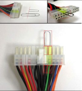
Зеленый провод – пусковой. Его нужно замкнуть с любым черным.
Вот так это выглядит на схеме:
Распиновка 20 пинового разъема блока питания
После того, как контакты замкнуты можно вставлять кабель питания в розетку. Обратите внимание, что если на задней стенке есть кнопка, она также должна быть включена.

Кнопка включения на блоке питания
Если блок рабочий, то признаком этого будет включение вентилятора охлаждения на нем.
Если при сканировании асик не видно
Иногда при сканировании сети асик не видно, в таком случае сбрасываем прошивку Antminer до заводских настроек (Hard reset).
- Выключаем питание
- На передней панели устройства нажимаем и удерживаем кнопку IP Report
- Включаем питание и держим кнопку пока не моргнут 2 индикатора на передней панели зеленый и красный
- Асик перезагрузится и его будет видно в сети
Передняя панель асика, стрелкой отмечена кнопка Ip Report (сброс до заводских настроек)
Если понадобится помощь в прошивке и настройке асика, звоните.
6.1. Ошибка при прошивке "Can not find signature"
4. Узнаем IP адрес асика
Находим устройство в сети. Для этого нам понадобится программа Advanced ip Scanner.
Скриншот программы Advanced ip Scanner.
- Заходим в браузер и в строку поиска вводим ip адрес, в нашем случае это 192.168.1.36.
- Нажимаем Enter
- Устройство запросит логин и пароль, по умолчанию логин и пароль root (одинаковые)
Скриншот входа в асик через интернет браузер.
6.2. Другие ошибки
1. Подключение асика
Первый шаг, который необходимо сделать – это подключить блок питания к майнеру Antminer S9 и вставить Ethernet кабель.

Antminer S9 с подключенным блоком питания APW3+. Стрелками показаны места подключения кабелей.
Similar Topics
Bitmain Antminer s9, s9k, s9j - 13,5-14,0 Th/s
Частенько натыкаюсь на китайских поставщиков Antminer S9, предлагающих б/у машинки. Предложения самые разные, ну и размышления по этому поводу соответственно тоже. Интересно мнение форумчан - опыт таких покупок, ну и насколько это рискованно и оправдано.
Ремонт: Bitmain Antminer s7, s9, l3+
Официальный сайт | Antminer. Все модели. Вопросы, помощь, обсуждение. В теме действуют все Правила форума! Перед тем как задать вопрос, посмотрите НОВИЧКИ Bits.Media, все сюда Уважайте своё и чужое время. Для обсуждения и поиска программ/драйверов пользуйтесь разделом Файлы. Статьи на bits.media: Полезное: (!) FAQ (часто задаваемые вопросы) -Как найти в продаже разъемы питания, какая маркировка
Bitmain t17, t17e
Привет, друзья. Я вернулся 🙂 есть хешборд t17. мой клиент сказал после того, как он почистил хэшборд, не запустился. поэтому я проверил это и обнаружил, что некоторые части, такие как 5-контактная микросхема и 1 резистор и 1 конденсатор, не находятся там. резистор и конденсатор не проблема. проблема в том, что 5 пин ic. я не могу найти номер детали. Кто-нибудь может мне помочь, пожалуйста?
Bitmain представил новый ASIC-майнер с водяным охлаждением
Крупнейший производитель майнингового оборудования Bitmain заявил о запуске в серийное производство самого мощного устройства в линейке своей продукции. Судя по страничке модели на сайте производителя, Antminer S19 XP Hyd действительно является наиболее мощным устройством для добычи биткоина в линейке Bitmain. Майнер выдает хэшрейт в 255 Тх\с при потреблении энергии 5 304 Вт. Эффективность устройства составляет 20.8 джоуля на терахэш. Стоит ASIC-майнер $19 890, а поставки должны начаться в
Для многих достаточно опытных пользователей персональных компьютеров не секрет, что любой блок питания может быть запущен без материнской платы путем соединения определенных контактов на главной 20/24 пиновой фишке.
Такая потребность может возникнуть тогда, когда нужно проверить работоспособность блока в ситуациях, в которых системник не реагирует на нажатие кнопки включения. Ведь именно он является первым подозреваемым в таких случаях.
В данной статье мы расскажем какие провода нужно замкнуть, чтобы компьютерных блок питания запустился.
7. Настройка асика Antminer S9
Админка прошитого асика.
- Выбираем вкладку Miner Configuration – Mining profiles
- Здесь вы можете выбрать готовые пресеты (настройки хешрейта и потребления электричества)
Будьте внимательны при выборе пресета! На воздухе максимальный разгон возможен до 16 THs, больше только в иммерсионном охлаждении.
- При настройке асика обязательно включите Asic Boost для уменьшения расхода электричества
- Настройте порог хэшрейта, чтобы когда он падает ниже заданного, асик перезагружался
- Выставить температуру отключения лезвий
- Нажимаем кнопку PreSave
Выбор пула в настройках асика.
Майнер перезагрузится, далее будет проходить автоматическая оптимизация работы чипов, это может занять около часа, во время данного периода асик будет перезагружаться – это нормально.
Поздравляем, асик Bitmain Antminer S9 прошит и готов к работе!
Какие контакты замкнуть для запуска блока питания?
Если нужно узнать работоспособность блока, то лучший способ это сделать – его принудительный запуск. Несмотря на то, что в случаях, когда нет реакции на нажатие кнопки включения системного блока, могут быть виновниками и кнопка включения и даже материнская плата.
Итак, для начала полностью обесточиваем блок. То есть вытаскиваем провод, идущий в розетку. После этого берем кусок проволоки или скрепку.
Далее соединяем контакт зеленого провода с любым черным. Выглядит это вот так:
Зеленый провод – пусковой. Его нужно замкнуть с любым черным.
Вот так это выглядит на схеме:
Распиновка 20 пинового разъема блока питания
После того, как контакты замкнуты можно вставлять кабель питания в розетку. Обратите внимание, что если на задней стенке есть кнопка, она также должна быть включена.
Кнопка включения на блоке питания
Если блок рабочий, то признаком этого будет включение вентилятора охлаждения на нем.
Content of this Volume: It mainly describes the troubleshooting of various faults of the power supply APW8, and how to use the test tool for accurate positioning.
※ The copyright of this article belongs to Bitmaintech Pte.Ltd. (Bitmain). The article shall solely be reprinted, extracted or used in any other ways with the permission of the copyright owner. Please contact Bitmain official customer service if there is any need of reprinting or quoting.
I. Requirements on the Maintenance Platform
3. The AC controllable power supply voltage regulator (output 200-250V, can limit 0-20A current) is used for APW8 power-on inspection. If there is no such condition, a 100W ordinary light bulb can also be strung on the AC fire line with mains. Be careful.
4. For electronic load (power 2KW, meet the voltage 0-50V), if there is no such condition, a resistive load that matches the APW8 can also be made.
5. The fluke 15b+ multimeter, suction gun, tweezers, V9-1.2 test jig and special power test card firmware (if there is condition, an oscilloscope can be configured).
6. Flux, lead-free tin wire, water for cleaning panel with anhydrous alcohol; water for cleaning panel is used to clean flux residue and appearance after maintenance.
7. Thermally conductive silicone grease (2500) is used to repair the thermal conduction between the MOS and the cooling fin, thermal conductive silicone (704 silica gel) is used for fixing and covering the glue damage at the original after the repair of the PCBA components
II. Requirements on Maintenance Operations
1. The maintenance personnel must have certain electronic knowledge, more than one year of maintenance experience, and a certain understanding of the working principle of switching power supply, and well master the soldering technology.
2. Before the product is opened and the PCBA panel is repaired, the large capacitor must be discharged, and the voltage must be measured with a multimeter (less than 5V discharge), and then the soldering operation can be performed! Be sure to confirm to avoid electric shock.
3. Pay attention to the working method when judging the circuit components. After replacing any device, the PCB panel has no obvious deformation, the soldering of bonding pad is reliable, and the replacement parts and the surrounding area have no problem such as insufficient parts, open circuit or short circuit.
4. After replacing the key components, the main circuit shall have no short circuit and other obvious abnormalities before the AC voltage test, otherwise there is a hidden danger of explosion.
5. It needs AC220V voltage to judge the circuit signal; pay attention to operational protection.
The following: Notes, key slogans
● Maintenance personnel qualifications must meet the specified requirements;
● Instruments and equipment used for maintenance must meet the specified requirements;
● The instruments and equipment for maintenance must be effectively grounded, and the maintenance environment must comply with anti-static requirements; Of course, it is better to wear an anti-static wrist strap.
● Materials used for maintenance must meet the specified requirements; in order to guarantee the accuracy and traceability of the materials used for maintenance, the materials used for maintenance must be the production materials for the corresponding models, and the material replacement must be confirmed;
2. The maintenance personnel shall use a special enclosure opener to open the enclosure of power adapter and repair, to avoid damage to the internal components of the product:
3. After the product is opened, it is required to discharge the high voltage capacitor;
4. E-waste waste generated during product maintenance cannot be arbitrarily dropped:
5. Bad products must have a repair process card and indicate the cause of the failure, and placed separately;
6. The repaired products must be well marked to distinguish.
7. The repaired products must be placed in the repaired area and shall be systematically tested before they can be stored.
III. The Principle and Structure of the Power Supply
1. Principle overview
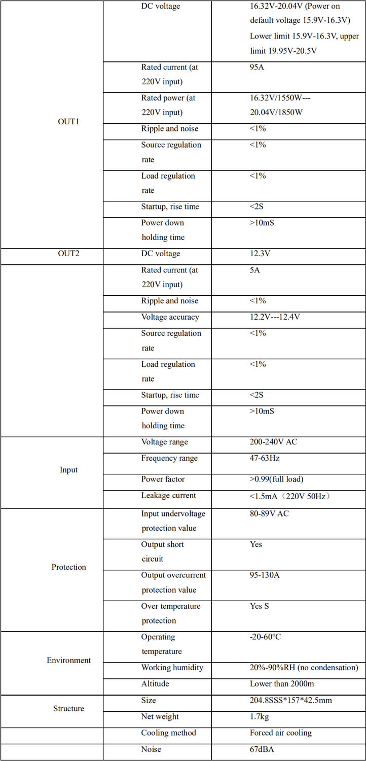
1.1 APW8 consists of 1 large panel, 2 fans and the upper and lower enclosures. The normal input AC220V has two DC output voltages, which are SB 12V respectively. The main voltage output is controlled by the PIC port and the miner communication, and different models’ DC voltage range is (8V-9.2V, 10V-11V, 16.32V-20.04V)
1.2 Performance characteristics and scope of use: S15, T15 with APW8 power supply 16.32V-20.04V as follows:
APW8 power supply is a high-efficiency DC power supply designed and manufactured by our company. It has single-phase AC input and two DC outputs:
1>. 16.32V-20.04V voltage adjustable output, the maximum current can reach 95A;
2>. 12V voltage fixed output, the current can reach 5A.
The adjustable output part of voltage can meet the common DC load use within 95A current of the adjustable voltage range, especially suitable for circumstances with strict requirements for power supply of servers and miners; the 12V voltage’s fixed output part can meet the use of control panel and cooling fin.
1.21 The are following characteristics:
●200-240V voltage input
●There is protection for undervoltage, short circuit, overload, over temperature, with
automatic recovery after fault removal
●The use of high-quality devices ensures stable and reliable products through reasonable
design, and can work at full load for a long time in a high temperature environment at 60°C or lower.
●Small size, high power density
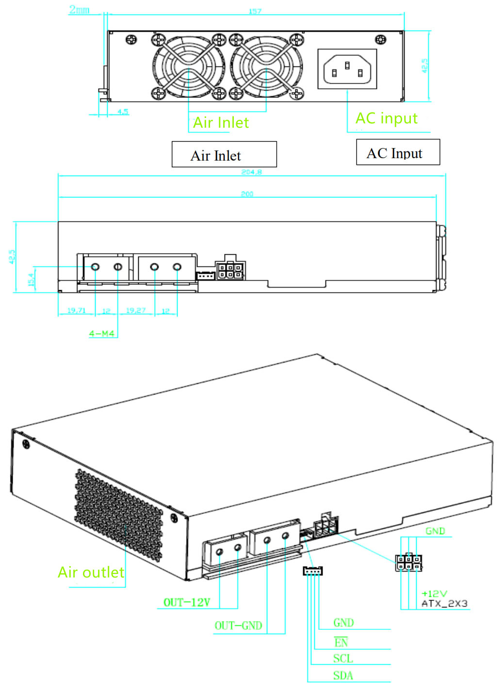
1.3 Appearance of APW8 Power Supply
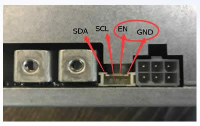
Note: If you need to turn on the default voltage 16.32V test, you can use the adapter cable to short connect the voltage Pin EN to GND.
● Distribution on the front panel of the power supply: one triangle-shape AC input interface two size-4028 high speed fans
●Distribution on the left side of the power supply: four PCB-33 copper soldering terminals with adjustable voltage output one 4Pin signal terminal one 12V fixed voltage output PCIE terminal
● Distribution on the rear panel of the power supply: 1 set of air outlets, forming the air outlet of the high-speed fan.
● The model of the AC input terminal on the power supply front panel is C14, and the AC input cable of the C13 interface is
● The 4Pin signal terminal is the interface between the external control panel and the power supply. The SDA/SCL is the I2Cprotocol, and can adjust the output voltage of the power supply through I2C. EN is the enable signal of the power supply, and the control panel can enable the power supply through EN, which is effective in low level.
● The output part of the adjustable voltage adopts four PCB-33 copper soldering terminals, 90-degree side foot binding posts, M4 high current horizontal fixed seat; the 2 terminals close to the air outlet are output positive poles, and 2 near signal terminals are output negative poles, the output line or output copper bar can be fixed on terminal by M4 screw, which is convenient and flexible to use.
● The output part of the 12V fixed voltage uses the PCIE output terminal. The PCIE output terminal diagram is as follows:
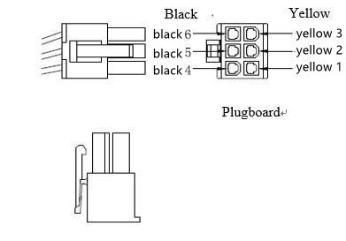
The PCIE output line consists of two color lines, the 12V positive line is yellow, and the negatives line is black.
Definition of 6PIN PCIE terminal positive and negative poles:
Positive pole: yellow 1, yellow 2, yellow 3
Negative pole: black 4, black 5, black 6
1.4 Parameters of APW8 Power Supply:
2. Maintenance ideas and cases of common faults
2.1 Block diagram for power basic principle
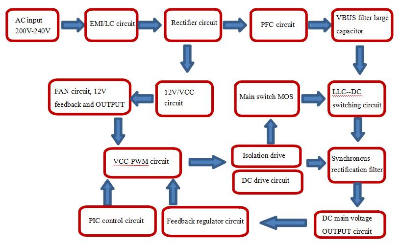
基本原理工作流程图: Basic principle work flow chart
AC 输入 200V- 240V: AC input of 200V-240V
EMI/LC 电路: EMI/LC circuit
整流电路: Rectifier circuit
PFC 电路: PFC circuit
VBUS 滤波大电容: VBUS filter large capacitor
FAN 电路、12V 反馈及 OUTPUT: FAN circuit, 12V feedback and OUTPUT
12V/VCC 电路: 12V/VCC circuit
主开关 MOS: Main switch MOS
LLC--DC 转换电路: LLC--DC switching circuit
VCC- PWM 电路: VCC-PWM circuit
隔离驱动: Isolation drive
DC 驱动电路: DC drive circuit
同步整流滤波: Synchronous rectification filter
PIC 控制电路: PIC control circuit
反馈稳压电路: Feedback regulator circuit
DC 主电压 OUTPUT 电路: DC main voltage OUTPUT circuit
2.2 Power PCBA board layout
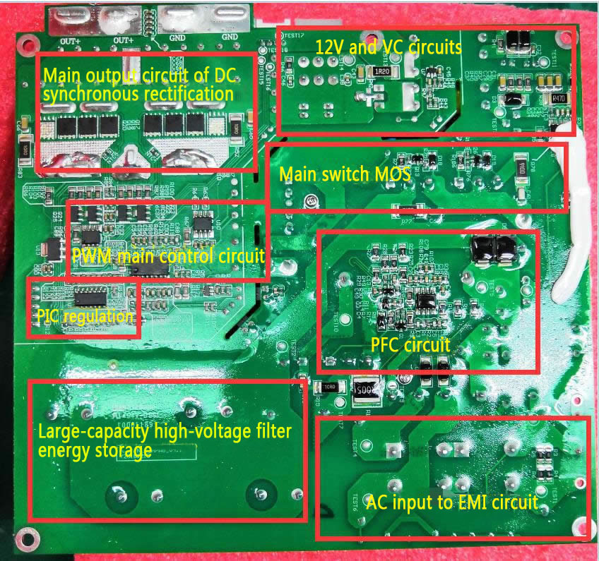
DC 同步整流主输出电路: Main output circuit of DC synchronous rectification
12V 及 VC 电路: 12V and VC circuits
主开关 MOS: Main switch MOS
PWM 主控电路: PWM main control circuit
PIC 调控: PIC regulation
PFC 电路: PFC circuit
大电容高压滤波储能: Large-capacity high-voltage filter energy storage
AC 输入 EMI 电路: AC input to EMI circuit
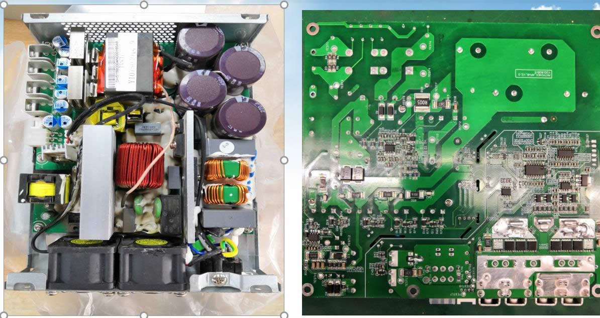
Physical picture, there will be small differences in product versions, but the principle is similar.
2.21 AC inputs EMI to PFC circuit schematic, focus on measuring whether F1 insurance, U2 rectifier bridge, Q4, D7, D5, D6 are damaged.
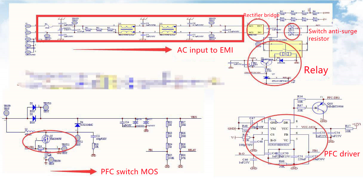
整流桥: Rectifier bridge
AC 输入EMI: AC input to EMI
开关防浪涌电阻: Switch anti-surge resistor
PFC 开关 MOS: PFC switch MOS
PFC 驱动: PFC driver
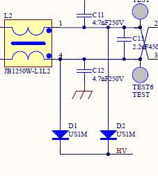
2.22 12V auxiliary circuit principle, focus on measuring whether voltage detection starts resistor R33, 47K and connecting with HV to D1, D2, and whether Q5, D8, D9, T1 is damaged.
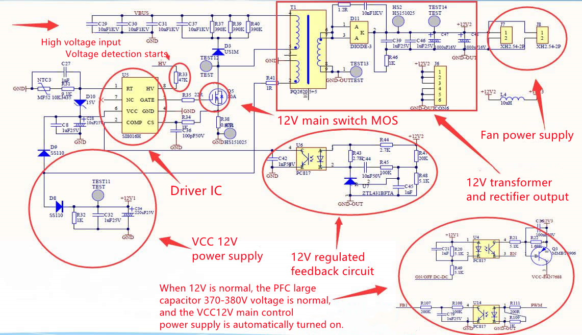
高电压输入: High voltage input
电压检测启动: Voltage detection starts
12V 主开关 MOS: 12V main switch MOS
驱动 IC: Driver IC
VCC 12V 供电: VCC 12V power supply
风扇供电: Fan power supply
12V 变压器及整流输出: 12V transformer and rectifier output
12V 稳压反馈电路: 12V regulated feedback circuit
12V 正常时,PFC 大电容 370-380V 电压正常,自动开 VCC12V 主控制供电: When 12V is normal, the PFC large capacitor 370-380V voltage is normal, and the VCC12V main control power supply is automatically turned on.
2.23 The main control PWM drive circuit, PIC control voltage regulation schematic diagram, focus on the main IC VCC power supply and drive transformer.
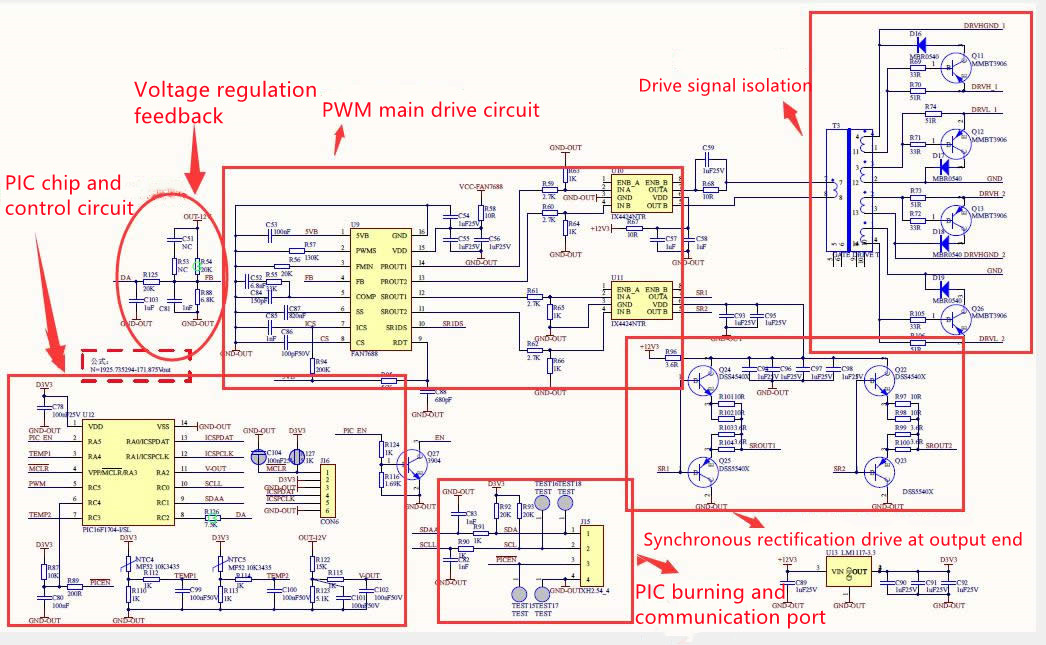
稳压反馈: Voltage regulation feedback
PWM 主驱动电路: PWM main drive circuit
PIC 芯片及控制电路: PIC chip and control circuit
PIC 烧录及通讯端口: PIC burning and communication port
输出端同步整流驱动: Synchronous rectification drive at output end
驱动信号隔离: Drive signal isolation
2.24 Main switch MOS and transformer conversion buck synchronous rectification DC filter output circuit, focus on the main switch MOS Q14, Q15, Q6, Q16, the output rectifier side positive and negative have no short circuit.
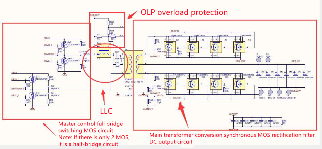
OLP 过载保护: OLP overload protection
主控全桥开关 MOS 电路: Master control full bridge switching MOS circuit
注:如只有 2 个 MOS 为半桥电路: Note: If there is only 2 MOS, it is a half-bridge circuit
主变压器转换同步 MOS 整 流 滤 波: Main transformer conversion synchronous MOS rectification filter
DC 输出电路: DC output circuit
2.25 Location of A side of SMD patch and B side of plug-in
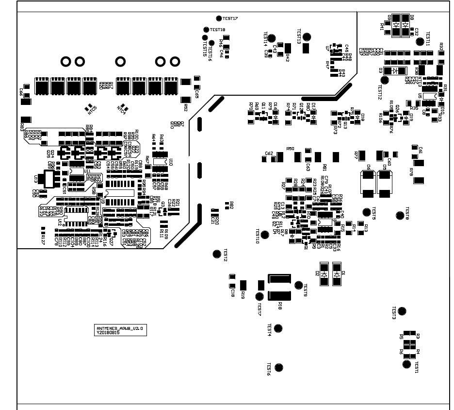
Figure 1 SMD patch side location
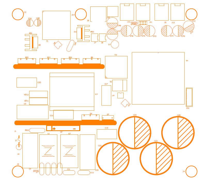
Figure 2 Plug-in side location
2.3 Maintenance steps
2.31. Check whether the appearance of the power supply is seriously damaged or deformed, and whether the DC fan and the AC socket are damaged.
2.32. Power on AC220V, check whether the fan is rotating normally, and use the multimeter to measure whether the output J6 terminal’s voltage is 12V (12.1V-12.50) to eliminate measuring error
2.33. Open the enclosure to check whether the components and solder surface have sparking phenomenon (focus on whether the R33 resistor is damaged), use a multimeter to detect whether the AC input terminal’s F1 fuse has open circuit, whether the U2 rectifier bridge; PFC MOS Q1, D7, D5, D6 have short circuit, whether the PWM circuit’s main switches MOS Q6, Q14, Q15, Q16 and output patches MOS Q17, Q18, Q19, Q20 have short circuit; if there is a short circuit, the component position should be checked and replaced, pay attention to the circuit resistance around bad bit MOS tube; the transistor may be damaged and needs to be replaced.
2.34. Detect whether the auxiliary 12V circuits U5, T1, Q5, D11 have short circuit or open circuit, and whether the surrounding components are burned, etc., replace if necessary.
2.35. If there is no abnormality in the above locations, the F1 fuse path is normal. After the AC is powered on, the DC fan rotates (if there is no rotation, check whether the fan socket has voltage of 12V, if the voltage is normal, replace the fan); the output terminal J6 has 12V voltage, measure whether there is DC370V-380V at both ends of PFC large capacitor C16 or C17, otherwise check whether U1, pin 7V VCC power supply has 12V or judge material damage and replace, if there is no abnormality, it needs to detect PWM circuit U9, U10, U11, whether supply VCC has 12V voltage or judge material damage and replace, and whether the T4 drive transformer is damaged.
2.36. other bad needs to be further analyzed and judged according to the skills of maintenance personnel, After the above check, the single power supply test main circuit DC output needs to be short connected to the J15 PIN 4-5, as EN-GND pin shown in the figure. Note that short connection errors may damage the chip. After the defective device is replaced and the soldering is correct, the AC220V test can be performed.
2.4 Diagram for electrical function test connection, PCBA main voltage measurement point.
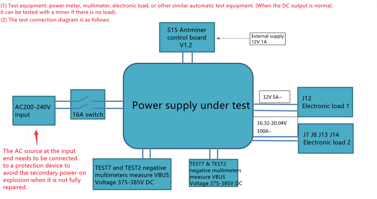
(1) Test equipment: power meter, multimeter, electronic load, or other similar automatic test equipment. (When the DC output is normal, it can be tested with a miner if there is no load).
(2) The test connection diagram is as follows:
S15 矿机控制板: S15 miner control panel
外供 12V 1A: External supply 12V 1A.
AC200-240V 输入: AC200-240V input
16A 开关: 16A switch
被测电源: Power supply under test
电子负载 1: Electronic load 1
电子负载 2: Electronic load 2
输入端 AC 源需接保护装置,以免未完全修好的开关电源二次上电炸机。
The AC source at the input end needs to be connected to a protection device to avoid the secondary power-on explosion when it is not fully repaired.
TEST7 与 TEST2 负极万用表量测 VBUS: TEST7 and TEST2 negative multimeters measure VBUS
电压 375-385V DC: Voltage 375-385V DC
TEST11 与 TEST7 负极万用表量测 VCC 12-13V: TEST11 and TEST7 negative multimeters measure VCC 12-13V
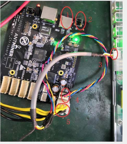
2.41 Diagram for S15 control panel V1.2 and APW8 power PIC port connection test, label 1 is the dedicated card test firmware, 2 is the DC voltage debugging high-low conversion button, 3 is the PIC communication port, 4 is the control panel socket, 5 is 12V power supply; note that yellow indicates positive and black indicates negative. Note: After the general power supply defective products are repaired, the power supply only needs to be short connected with the PIC communication J15 port EN-GND pin, and if there is voltage output 16V, it is normal, and the following single test for the control panel is not requried (when the PIC single chip is damaged, or when the firmware is abnormal, it needs to test a small panel before re-burning), and the corresponding miner test can be directly installed.
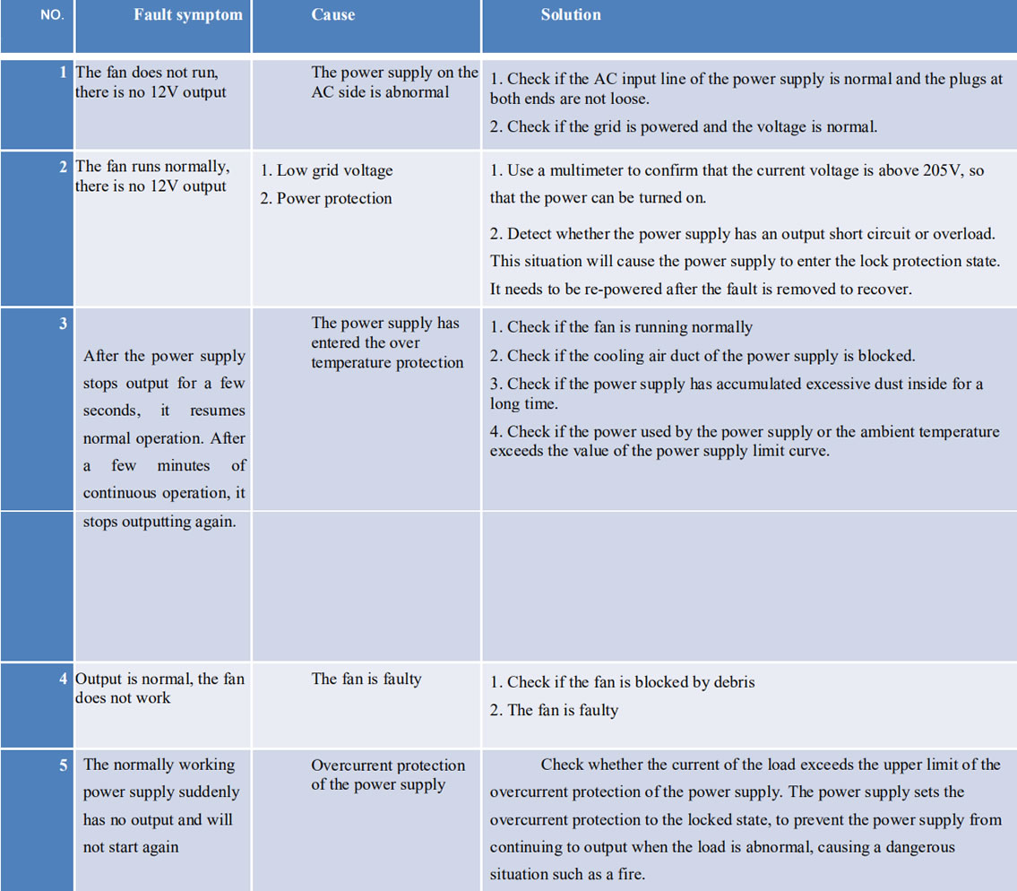
2.5 Simple judgment and maintenance of common faults of mine power supply
2.6 After the power supply maintenance test is normal, it is required to operate normally for 2 hours with the rated load of 80% (80A) or more before it can be used by the client.

Antminer S9 – самый популярный асик с 2016 года. От других видов майнеров отличается большей надежностью, высокой ремонтопригодностью и доступной ценой (на март 2020 года $130 за б/у в Москве). После выхода устройства на рынок стали появляться первые прошивки. Они нужны для того, чтобы оптимизировать работу асика под вашу цену электричества и условия работы.
Основные плюсы кастомной прошивки ASIC:
- Увеличение доходности. Благодаря технологии асикбуст и оптимизации прошивки энергоэффективность асика увеличиться
- Готовые профили разгона и даунвольта (пресеты). Легко и просто настраивается выбором профиля исходя из мощности вашего блока питания и системы охлаждения
- Возможность отключения вентиляторов при иммерсионном охлаждении (не нужны эмуляторы вентиляторов)
С помощью этого гайда вы сможете быстро и легко прошить Antminer S9.
Перед тем, как начать работу убедитесь, что у вас готовы все необходимые элементы для подключения:
Последние посетители 0 пользователей онлайн
2. Узнаем версию прошивки
- Если установлена прошивка 2018 года или раньше, то в этом асике нет защиты от перезаписи и прошивать с флешки не обязательно, переходим сразу к пункту 4
- Если установлена прошивка до июня 2019 года, то можно убрать защиту используя файл "signature" (скачать файл signature для снятия цифровой подписи) и далее уже загрузить нашу прошивку
- Если установлена прошивка с 2019 года, то установка прошивки возможна только через SD карту

Версия прошивки на примере асика Antminer S9. В этом случае это 2017 год
Войти
Уже есть аккаунт? Войти в систему.
3. Записываем образ через флешку
- Скачиваем образ для нужного асика (S17, S17+, S17 Pro, T17, T17+, S9, S9i, S9j, S9d, T9+, L3+ и L3++), на странице ссылка "скачать образ"
- Переносим файлы и папки из архива на SD карту
- Выключаем асик и вставляем SD карту с записанным образом
- Ждем 3 минуты пока не начнут мигать 2 лампы (зеленая и красная)
- Выключаем асик, вытаскиваем SD и включаем асик
- В разделе system должна отобразиться прошивка MP TEST FIRMWARE
- Используем файл UNLOCK SSH и инструкцию внутри (Внимание web пароль : admin)
правильно заполняйте файл settings для разблокировки ssh ( пароли admin/admin)
Читайте также: