
Raspberry pi zero распиновка usb
The latest version of the Compute Module is the Compute Module 4 (CM4). It is the recommended Compute Module for all current and future development.
There is also a KiCAD PCB design set available:
Видеообзор платформы
Cлот для microSD
Разъём питания
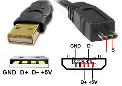
Разъём формфактора micro-USB предназначен для питания Raspberry Pi.
Потребляемый ток может достигать до 3 ампер. Для стабильной работы используйте зарядник 5 В совместно с кабелем USB (A — Micro USB).
Порты ввода/вывода
В отличие от платформ с логическим напряжением 5 В, напряжение логических уровней Raspberry Pi является 3,3 В. Выходы для логической единицы выдают 3,3 В, а в режиме входа ожидают принимать не более 3,3 В. Более высокое напряжение может повредить одноплатник.
Будьте внимательны при подключении периферии: убедитесь, что она может корректно функционировать в этом диапазоне напряжений.
Цифровые входы/выходы: На плате расположено 26 контактов пинов ввода-вывода GPIO.
Логический уровень единицы — 3,3 В, нуля — 0 В. Максимальный ток выхода — 16 мА. В мире Raspberry Pi закрепилось три нумерации контактов:
GPIO (Интерфейс ввода/вывода общего назначения (англ. general-purpose input/output ) это интерфейс для общения с любыми внешними устройствами и управления ими. Контакты GPIO могут выступать как в роли входа, так и в роли выхода.
Compute Module 4 Bootloader
The default bootloader configuration on CM4 is designed to support bringup and development on a Compute Module 4 IO board and the software version flashed at manufacture may be older than the latest release. For final products please consider:-
Selecting and verifying a specific bootloader release. The version in the usbboot repo is always a recent stable release.
Configuring the boot device (e.g. network boot). See BOOT_ORDER section in the bootloader configuration guide.
Enabling hardware write protection on the bootloader EEPROM to ensure that the bootloader can’t be modified on remote/inaccessible products.
N.B. The Compute Module 4 ROM never runs recovery.bin from SD/EMMC and the rpi-eeprom-update service is not enabled by default. This is necessary because the EMMC is not removable and an invalid recovery.bin file would prevent the system from booting. This can be overridden and used with self-update mode where the bootloader can be updated from USB MSD or Network boot. However, self-update mode is not an atomic update and therefore not safe in the event of a power failure whilst the EEPROM was being updated.
Modifying the bootloader configuration
To modify the CM4 bootloader configuration:-
Replace pieeprom.original.bin if a specific bootloader release is required.
Edit the default boot.conf bootloader configuration file. Typically, at least the BOOT_ORDER must be updated:-
For network boot BOOT_ORDER=0xf2
For SD/EMMC boot BOOT_ORDER=0xf1
For USB boot failing over to EMMC BOOT_ORDER=0xf15
Run ./update-pieeprom.sh to update the EEPROM image pieeprom.bin image file.
If EEPROM write protection is required then edit config.txt and add eeprom_write_protect=1 . Hardware write-protection must be enabled via software and then locked by pulling the EEPROM_nWP pin low.
Run ../rpiboot -d . to update the bootloader using the updated EEPROM image pieeprom.bin
The pieeprom.bin file is now ready to be flashed to the Compute Module 4.
Flashing the bootloader EEPROM - Compute Module 4
To flash the bootloader EEPROM follow the same hardware setup as for flashing the EMMC but also ensure EEPROM_nWP is NOT pulled low. Once complete EEPROM_nWP may be pulled low again.
Copy to Clipboard
Attaching and Enabling Peripherals
This guide is designed to help developers using the Compute Module 1 (and Compute Module 3) get to grips with how to wire up peripherals to the Compute Module pins, and how to make changes to the software to enable these peripherals to work correctly.
The Compute Module 1 (CM1) and Compute Module 3 (CM3) contain the Raspberry Pi BCM2835 (or BCM2837 for CM3) system on a chip (SoC) or 'processor', memory, and eMMC. The eMMC is similar to an SD card but is soldered onto the board. Unlike SD cards, the eMMC is specifically designed to be used as a disk and has extra features that make it more reliable in this use case. Most of the pins of the SoC (GPIO, two CSI camera interfaces, two DSI display interfaces, HDMI etc) are freely available and can be wired up as the user sees fit (or, if unused, can usually be left unconnected). The Compute Module is a DDR2 SODIMM form-factor-compatible module, so any DDR2 SODIMM socket should be able to be used
To use the Compute Module, a user needs to design a (relatively simple) 'motherboard' which can provide power to the Compute Module (3.3V and 1.8V at minimum), and which connects the pins to the required peripherals for the user’s application.
Raspberry Pi provides a minimal motherboard for the Compute Module (called the Compute Module IO Board, or CMIO Board) which powers the module, brings out the GPIO to pin headers, and brings the camera and display interfaces out to FFC connectors. It also provides HDMI, USB, and an 'ACT' LED, as well as the ability to program the eMMC of a module via USB from a PC or Raspberry Pi.
This guide first explains the boot process and how Device Tree is used to describe attached hardware; these are essential things to understand when designing with the Compute Module. It then provides a worked example of attaching an I2C and an SPI peripheral to a CMIO (or CMIO V3 for CM3) Board and creating the Device Tree files necessary to make both peripherals work under Linux, starting from a vanilla Raspberry Pi OS image.
Steps to Flash the eMMC
To flash the Compute Module eMMC, you either need a Linux system (a Raspberry Pi is recommended, or Ubuntu on a PC) or a Windows system (Windows 10 is recommended). For BCM2837 (CM3), a bug which affected the Mac has been fixed, so this will also work.
Разъём питания
Разъём формфактора micro-USB предназначен для питания Raspberry Pi.
Потребляемый ток может достигать до 3 ампер. Для стабильной работы используйте зарядник 5 В совместно с кабелем USB (A — Micro USB).
Порты ввода/вывода
В отличие от платформ с логическим напряжением 5 В, напряжение логических уровней Raspberry Pi является 3,3 В. Выходы для логической единицы выдают 3,3 В, а в режиме входа ожидают принимать не более 3,3 В. Более высокое напряжение может повредить одноплатник.
Будьте внимательны при подключении периферии: убедитесь, что она может корректно функционировать в этом диапазоне напряжений.
Цифровые входы/выходы: На плате расположено 26 контактов пинов ввода-вывода GPIO.
Логический уровень единицы — 3,3 В, нуля — 0 В. Максимальный ток выхода — 16 мА. В мире Raspberry Pi закрепилось три нумерации контактов:
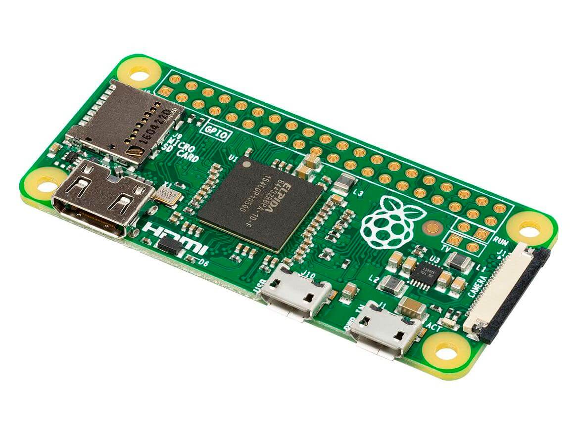
Raspberry Pi Zero — компактная версия одноплатного компьютера. На плате размером с флешку поместился бутерброд из чипа Broadcom BCM2835 с оперативной памятью объёмом 512 МБ, порты ввода-вывода, слот для microSD-карты и мультимедийные интерфейсы.
Композитный видео выход
Выход аналогового видео сигнала в виде двух пинов под пайку. Сигнал используется для подключения к «тёплым ламповым телевизорам» через RCA-разъём или в просто народе «тюльпан».
Mini-HDMI порт
Разъём предназначен для вывода цифрового видео и звука на мультимедийные устройства. Для коммуникации понадобиться HDMI-кабель с переходником.
Пины питания
3V3: Пин от стабилизатора напряжения с выходом 3,3 вольта и максимальных током 1 А. Регулятор обеспечивает питание процессора и других элементов платы.
Cлот для microSD
Примеры работы
Чип BCM2835
Сердце компьютера Raspberry Pi Zero — чип Broadcom BCM2835, который выполнен по технологии SoC (англ. System-on-a-Chip — система на кристалле). Кристалл включает в себя процессор CPU ARM1176JZ-F разогнанный до частоты 1 ГГц и графический двухъядерный сопроцессор GPU VideoCore IV с частотой 250 МГц.
Сверху на чипе BCM2835 по технологии PoP (англ. Package-on-Package — корпус на корпусе) расположена оперативная память Elpida B4432BBPA-10-F объёмом 512 МБ.
Элементы платы

Композитный видео выход
Выход аналогового видео сигнала в виде двух пинов под пайку. Сигнал используется для подключения к «тёплым ламповым телевизорам» через RCA-разъём или в просто народе «тюльпан».
Распиновка разъемов GPIO Raspberry Pi
Внимание!
В отличие от плат Arduino, напряжение логических уровней Raspberry Pi является 3,3 В. Максимальное напряжение, которое могут выдержать вход/выходы составляет 3,3 В а не 5 В. Подав напряжение, например 5 В, можно вывести одноплатник из строя.

Mini-HDMI порт
Разъём предназначен для вывода цифрового видео и звука на мультимедийные устройства. Для коммуникации понадобиться HDMI-кабель с переходником.
Ethernet-разъём
10/100 Мбит Ethernet-разъем для подключения к сети через RJ45 патч-корд витой пары.
dt-blob.bin
When start.elf runs, it first reads something called dt-blob.bin . This is a special form of Device Tree blob which tells the GPU how to (initially) set up the GPIO pin states, and also any information about GPIOs/peripherals that are controlled (owned) by the GPU, rather than being used via Linux on the ARM. For example, the Raspberry Pi Camera peripheral is managed by the GPU, and the GPU needs exclusive access to an I2C interface to talk to it, as well as a couple of control pins. I2C0 on most Raspberry Pi Boards and Compute Modules is nominally reserved for exclusive GPU use. The information on which GPIO pins the GPU should use for I2C0, and to control the camera functions, comes from dt-blob.bin .
minimal-cm-dt-blob.dts is an example .dts device tree file that sets up the HDMI hot plug detect and ACT LED and sets all other GPIOs to be inputs with default pulls.
To compile the minimal-cm-dt-blob.dts to dt-blob.bin use the Device Tree Compiler dtc :
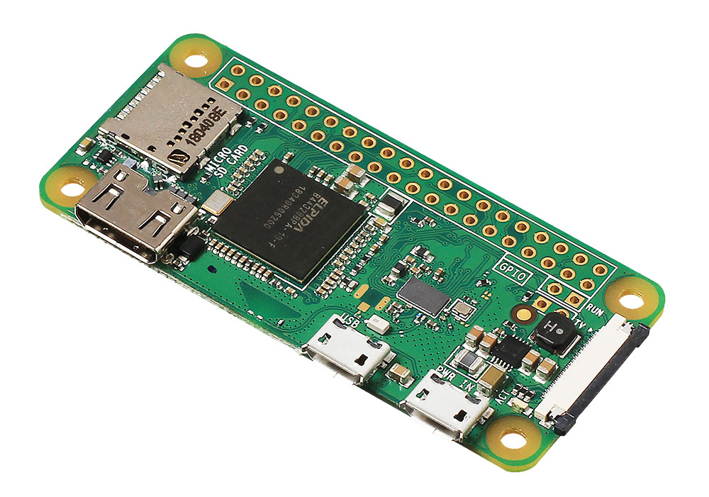
Raspberry Pi Zero W — компактная версия одноплатного компьютера. На плате размером с флешку поместился бутерброд из чипа Broadcom BCM2835 с оперативной памятью объёмом 512 МБ, порты ввода-вывода, слот для microSD-карты и мультимедийные интерфейсы.
Пины питания
3V3: Пин от стабилизатора напряжения с выходом 3,3 вольта и максимальных током 1 А. Регулятор обеспечивает питание процессора и других элементов платы.
Пины питания
3V3: Пин от стабилизатора напряжения с выходом 3,3 вольта и максимальных током 1 А. Регулятор обеспечивает питание процессора и других элементов платы.
Видеообзор платформы
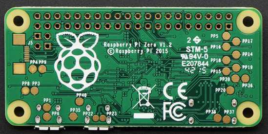
Распиновка
На Raspberry Pi Zero расположены два ряда по 20 контактов в виде луженных отверстий.

Device Tree
Device Tree is a special way of encoding all the information about the hardware attached to a system (and consequently required drivers).
On a Raspberry Pi or Compute Module there are several files in the first FAT partition of the SD/eMMC that are binary 'Device Tree' files. These binary files (usually with extension .dtb ) are compiled from human-readable text descriptions (usually files with extension .dts ) by the Device Tree compiler.
On a standard Raspberry Pi OS image in the first (FAT) partition you will find two different types of device tree files, one is used by the GPU only and the rest are standard ARM device tree files for each of the BCM283x based Raspberry Pi products:
dt-blob.bin (used by the GPU)
bcm2709-rpi-2-b.dtb (Used for Raspberry Pi 2 Model B)
bcm2710-rpi-3-b.dtb (Used for Raspberry Pi 3 Model B)
bcm2710-rpi-cm3.dtb (Used for Raspberry Pi Compute Module 3)
During boot, the user can specify a specific ARM device tree to use via the device_tree parameter in config.txt , for example adding the line device_tree=mydt.dtb to config.txt where mydt.dtb is the dtb file to load instead of one of the standard ARM dtb files. While a user can create a full device tree for their Compute Module product, the recommended way to add hardware is to use overlays (see next section).
In addition to loading an ARM dtb, start.elf supports loading additional Device Tree 'overlays' via the dtoverlay parameter in config.txt , for example adding as many dtoverlay=myoverlay lines as required as overlays to config.txt , noting that overlays live in /overlays and are suffixed -overlay.dtb e.g. /overlays/myoverlay-overlay.dtb . Overlays are merged with the base dtb file before the data is passed to the Linux kernel when it starts.
Mini-HDMI порт
Разъём предназначен для вывода цифрового видео и звука на мультимедийные устройства. Для коммуникации понадобиться HDMI-кабель с переходником.
Установка и настройка
Для начала работы с одноплатником Raspberry Pi Zero прочитайте мануал по настройке Raspberry Pi
Older Products
Design data for the Compute Module camera/display adapter board (CMCDA):
Разъём питания
Разъём формфактора micro-USB предназначен для питания Raspberry Pi.
Потребляемый ток может достигать до 3 ампер. Для стабильной работы используйте зарядник 5 В совместно с кабелем USB (A — Micro USB).
Элементы платы

Разъём подключения периферии
Порт формфактора micro-USB для подключения мультимедийных устройств со стандартным USB-разъёмом.
Для коммуникации понадобится OTG-переходник USB (F) — USB Micro (M). Для подключения нескольких устройств используйте USB-хаб.
Older Products
Raspberry Pi CM1, CM3 and CM3L are supported products with an End-of-Life (EOL) date no earlier than January 2026. The Compute Module 3+ offers improved thermal performance, and a wider range of Flash memory options.
Raspberry Pi CM3+ and CM3+ Lite are supported prodicts with an End-of-Life (EOL) date no earlier than January 2026.
Schematics for the Compute Module 1, 3 and 3L
Schematics for the Compute Module IO board (CMIO):
CMIO Rev 3.0 (Supports CM1, CM3, CM3L, CM3+ and CM3+L)
Schematics for the Compute Module camera/display adapter board (CMCDA):
Under Voltage Detection
Schematic for an under-voltage detection circuit, as used in older models of Raspberry Pi:

Design Files for CMIO Boards
Чип BCM2835
Сердце компьютера Raspberry Pi Zero — чип Broadcom BCM2835, который выполнен по технологии SoC (англ. System-on-a-Chip — система на кристалле). Кристалл включает в себя процессор CPU ARM1176JZ-F разогнанный до частоты 1 ГГц и графический двухъядерный сопроцессор GPU VideoCore IV с частотой 250 МГц.
Сверху на чипе BCM2835 по технологии PoP (англ. Package-on-Package — корпус на корпусе) расположена оперативная память Elpida B4432BBPA-10-F объёмом 512 МБ.
Установка и настройка
Для начала работы с одноплатником Raspberry Pi Zero прочитайте мануал по подготовке Raspberry Pi.
Установка и настройка
Для начала работы с одноплатником Raspberry Pi Zero прочитайте мануал по подготовке Raspberry Pi.
Порты ввода/вывода
В отличие от платформ с логическим напряжением 5 В, напряжение логических уровней Raspberry Pi является 3,3 В. Выходы для логической единицы выдают 3,3 В, а в режиме входа ожидают принимать не более 3,3 В. Более высокое напряжение может повредить одноплатник.
Будьте внимательны при подключении периферии: убедитесь, что она может корректно функционировать в этом диапазоне напряжений.
Цифровые входы/выходы: На плате расположено 26 контактов пинов ввода-вывода GPIO.
Логический уровень единицы — 3,3 В, нуля — 0 В. Максимальный ток выхода — 16 мА. В мире Raspberry Pi закрепилось три нумерации контактов:
Raspberry Pi Zero — компактная версия одноплатного компьютера. На плате размером с флешку поместился бутерброд из чипа Broadcom BCM2835 с оперативной памятью объёмом 512 МБ, порты ввода-вывода, слот для microSD-карты и мультимедийные интерфейсы.
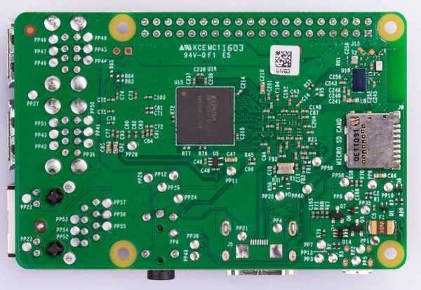
Распиновка тестовых точек на RaspberryPi
Ниже приведен список контрольных точек, которые можно найти на малине Pi 2, 3, а некоторые также на B+, Zero.
Благодаря использованию мультиметра эти контрольные точки могут помочь в устранении проблем с оборудованием.
Регулятор напряжения
Двухканальный импульсный понижающий регулятор напряжения PAM2306AYPKE с выходами 3,3 В и 1,8 В. Максимальный ток каждого канала 1 A.
Регулятор напряжения
Двухканальный импульсный понижающий регулятор напряжения PAM2306AYPKE с выходами 3,3 В и 1,8 В. Максимальный ток каждого канала 1 A.
Older Products
Raspberry Pi CM1, CM3 and CM3L are supported products with an End-of-Life (EOL) date no earlier than January 2026. The Compute Module 3+ offers improved thermal performance, and a wider range of Flash memory options.
Raspberry Pi CM3+ and CM3+ Lite are supported prodicts with an End-of-Life (EOL) date no earlier than January 2026.
Schematics for the Compute Module 1, 3 and 3L
Schematics for the Compute Module IO board (CMIO):
CMIO Rev 3.0 (Supports CM1, CM3, CM3L, CM3+ and CM3+L)
Schematics for the Compute Module camera/display adapter board (CMCDA):
Under Voltage Detection
Schematic for an under-voltage detection circuit, as used in older models of Raspberry Pi:
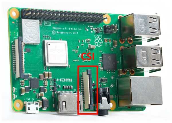
Разъём камеры (CSI)
Разъём для подключения камеры Raspberry Pi.
Разъем для камеры на RPi Zero отличается от полноценной Raspberry Pi. Используйте специальную камеру для Raspberry Pi Zero
Регулятор напряжения
Двухканальный импульсный понижающий регулятор напряжения PAM2306AYPKE с выходами 3,3 В и 1,8 В. Максимальный ток каждого канала 1 A.
Распиновка
На Raspberry Pi Zero расположены два ряда по 20 контактов в виде луженных отверстий.
Композитный видео выход
Выход аналогового видео сигнала в виде двух пинов под пайку. Сигнал используется для подключения к «тёплым ламповым телевизорам» через RCA-разъём или в просто народе «тюльпан».
Setting up the CMIO board
Compute Module 4
Ensure the Compute Module is fitted correctly installed on the IO board. It should lie flat on the IO board.
Make sure that nRPI_BOOT which is on J2 ( disable eMMC Boot ) on the IO board jumper is fitted
Use a micro USB cable to connect the micro USB slave port J11 on IO board to the host device.
Do not power up yet.
Compute Module 1 and 3
Ensure the Compute Module itself is correctly installed on the IO board. It should lie parallel with the board, with the engagement clips clicked into place.
Make sure that J4 (USB SLAVE BOOT ENABLE) is set to the 'EN' position.
Use a micro USB cable to connect the micro USB slave port J15 on IO board to the host device.
Do not power up yet.
For Windows Users
Under Windows, an installer is available to install the required drivers and boot tool automatically. Alternatively, a user can compile and run it using Cygwin and/or install the drivers manually.
Windows Installer
For those who just want to enable the Compute Module eMMC as a mass storage device under Windows, the stand-alone installer is the recommended option. This installer has been tested on Windows 10 32-bit and 64-bit, and Windows XP 32-bit.
Please ensure you are not writing to any USB devices whilst the installer is running.
Download and run the Windows installer to install the drivers and boot tool.
Plug your host PC USB into the USB SLAVE port, making sure you have setup the board as described above.
Apply power to the board; Windows should now find the hardware and install the driver.
Once the driver installation is complete, run the RPiBoot.exe tool that was previously installed.
After a few seconds, the Compute Module eMMC will pop up under Windows as a disk (USB mass storage device).
Building rpiboot on your host system (Cygwin/Linux)
We will be using Git to get the rpiboot source code, so ensure Git is installed. In Cygwin, use the Cygwin installer. On a Raspberry Pi or other Debian-based Linux machine, use the following command:
Copy to Clipboard
Git may produce an error if the date is not set correctly. On a Raspberry Pi, enter the following to correct this:
Copy to Clipboard
where MM is the month, DD is the date, and hh and mm are hours and minutes respectively.
Clone the usbboot tool repository:
Copy to Clipboard
libusb must be installed. If you are using Cygwin, please make sure libusb is installed as previously described. On Raspberry Pi OS or other Debian-based Linux, enter the following command:
Copy to Clipboard
Now build and install the usbboot tool:
Copy to Clipboard
Run the usbboot tool and it will wait for a connection:
Copy to Clipboard
Now plug the host machine into the Compute Module IO board USB slave port and power the CMIO board on. The rpiboot tool will discover the Compute Module and send boot code to allow access to the eMMC.
For more information run
Copy to Clipboard
Writing to the eMMC (Windows)
After rpiboot completes, a new USB mass storage drive will appear in Windows. We recommend following this guide and using Win32DiskImager to write images to the drive, rather than trying to use /dev/sda etc. from Cygwin.
Make sure J4 (USB SLAVE BOOT ENABLE) / J2 (nRPI_BOOT) is set to the disabled position and/or nothing is plugged into the USB slave port. Power cycling the IO board should now result in the Compute Module booting from eMMC.
Writing to the eMMC (Linux)
After rpiboot completes, you will see a new device appear; this is commonly /dev/sda on a Raspberry Pi but it could be another location such as /dev/sdb , so check in /dev/ or run lsblk before running rpiboot so you can see what changes.
You now need to write a raw OS image (such as Raspberry Pi OS) to the device. Note the following command may take some time to complete, depending on the size of the image: (Change /dev/sdX to the appropriate device.)
Copy to Clipboard
Once the image has been written, unplug and re-plug the USB; you should see two partitions appear (for Raspberry Pi OS) in /dev . In total, you should see something similar to this:
Copy to Clipboard
The /dev/sdX1 and /dev/sdX2 partitions can now be mounted normally.
Make sure J4 (USB SLAVE BOOT ENABLE) / J2 (nRPI_BOOT) is set to the disabled position and/or nothing is plugged into the USB slave port. Power cycling the IO board should now result in the Compute Module booting from eMMC.
Распиновка
На Raspberry Pi Zero расположены два ряда по 20 контактов в виде луженных отверстий.
Примеры работы
Cлот для microSD
Flashing the Compute Module eMMC
The Compute Module has an on-board eMMC device connected to the primary SD card interface. This guide explains how to write data to the eMMC storage using a Compute Module IO board.
Please also read the section in the Compute Module Datasheets
BCM283x Boot Process
BCM283x devices consist of a VideoCore GPU and ARM CPU cores. The GPU is in fact a system consisting of a DSP processor and hardware accelerators for imaging, video encode and decode, 3D graphics, and image compositing.
In BCM283x devices, it is the DSP core in the GPU that boots first. It is responsible for general setup and housekeeping before booting up the main ARM processor(s).
The BCM283x devices as used on Raspberry Pi and Compute Module boards have a three-stage boot process:
The GPU DSP comes out of reset and executes code from a small internal ROM (the boot ROM). The sole purpose of this code is to load a second stage boot loader via one of the external interfaces. On a Raspberry Pi or Compute Module, this code first looks for a second stage boot loader on the SD card (eMMC); it expects this to be called bootcode.bin and to be on the first partition (which must be FAT32). If no SD card is found or bootcode.bin is not found, the Boot ROM sits and waits in 'USB boot' mode, waiting for a host to give it a second stage boot loader via the USB interface.
The second stage boot loader ( bootcode.bin on the sdcard or usbbootcode.bin for usb boot) is responsible for setting up the LPDDR2 SDRAM interface and various other critical system functions and then loading and executing the main GPU firmware (called start.elf , again on the primary SD card partition).
Разъём подключения периферии
Порт формфактора micro-USB для подключения мультимедийных устройств со стандартным USB-разъёмом.
Для коммуникации понадобится OTG-переходник USB (F) — USB Micro (M). Для подключения нескольких устройств используйте USB-хаб.
Разъём камеры (CSI)
Разъём для подключения камеры Raspberry Pi.
Разъем для камеры на RPi Zero отличается от полноценной Raspberry Pi. Используйте специальную камеру для Raspberry Pi Zero
Разъёмы 4×USB2.0
USB -хаб с четырьмя разъёмами для подключения клавиатуры, мыши, флешек и других USB -устройств.

Чип BCM2835
Сердце компьютера Raspberry Pi Zero — чип Broadcom BCM2835, который выполнен по технологии SoC (англ. System-on-a-Chip — система на кристалле). Кристалл включает в себя процессор CPU ARM1176JZ-F разогнанный до частоты 1 ГГц и графический двухъядерный сопроцессор GPU VideoCore IV с частотой 250 МГц.
Сверху на чипе BCM2835 по технологии PoP (англ. Package-on-Package — корпус на корпусе) расположена оперативная память Elpida B4432BBPA-10-F объёмом 512 МБ.
Troubleshooting
For a small percentage of Raspberry Pi Compute Module 3s, booting problems have been reported. We have traced these back to the method used to create the FAT32 partition; we believe the problem is due to a difference in timing between the BCM2835/6/7 and the newer eMMC devices. The following method of creating the partition is a reliable solution in our hands.
Copy to Clipboard
Видеообзор платформы
Compute Module IO board for CM4
Design data for the Compute Module 4 IO board can be found in its datasheet:
There is also a KiCAD PCB design set available:
Примеры работы
Разъём подключения периферии
Порт формфактора micro-USB для подключения мультимедийных устройств со стандартным USB-разъёмом.
Для коммуникации понадобится OTG-переходник USB (F) — USB Micro (M). Для подключения нескольких устройств используйте USB-хаб.
Разъём камеры (CSI)
Разъём для подключения камеры Raspberry Pi.
Разъем для камеры на RPi Zero отличается от полноценной Raspberry Pi. Используйте специальную камеру для Raspberry Pi Zero
Таблица распиновки GPIO pin (WiringPi Pin)

BCM283x GPIOs
BCM283x has three banks of General-Purpose Input/Output (GPIO) pins: 28 pins on Bank 0, 18 pins on Bank 1, and 8 pins on Bank 2, making 54 pins in total. These pins can be used as true GPIO pins, i.e. software can set them as inputs or outputs, read and/or set state, and use them as interrupts. They also can be set to 'alternate functions' such as I2C, SPI, I2S, UART, SD card, and others.
On a Compute Module, both Bank 0 and Bank 1 are free to use. Bank 2 is used for eMMC and HDMI hot plug detect and ACT LED / USB boot control.
It is useful on a running system to look at the state of each of the GPIO pins (what function they are set to, and the voltage level at the pin) so that you can see if the system is set up as expected. This is particularly helpful if you want to see if a Device Tree is working as expected, or to get a look at the pin states during hardware debug.
Raspberry Pi provides the raspi-gpio package which is a tool for hacking and debugging GPIO
To install raspi-gpio :
Copy to Clipboard
If apt can’t find the raspi-gpio package, you will need to do an update first:
Copy to Clipboard
To get help on raspi-gpio , run it with the help argument:
Copy to Clipboard
For example, to see the current function and level of all GPIO pins use:
Copy to Clipboard
Copy to Clipboard
Элементы платы
Читайте также: