
Port fast ethernet cisco что это
The documentation set for this product strives to use bias-free language. For the purposes of this documentation set, bias-free is defined as language that does not imply discrimination based on age, disability, gender, racial identity, ethnic identity, sexual orientation, socioeconomic status, and intersectionality. Exceptions may be present in the documentation due to language that is hardcoded in the user interfaces of the product software, language used based on RFP documentation, or language that is used by a referenced third-party product. Learn more about how Cisco is using Inclusive Language.
Understanding How PortFast BPDU Guard Works
To prevent loops from occurring in a network, the PortFast mode is supported only on nontrunking access ports because these ports typically do not transmit or receive BPDUs. The most secure implementation of PortFast is to enable it only on ports that connect end stations to switches. Because PortFast can be enabled on nontrunking ports connecting two switches, spanning tree loops can occur because BPDUs are still being transmitted and received on those ports.
PortFast BPDU guard prevents loops by moving a nontrunking port into an errdisable state when a BPDU is received on that port. When you enable BPDU guard on the switch, spanning tree shuts down PortFast-configured interfaces that receive BPDUs instead of putting them into the spanning tree blocking state. In a valid configuration, PortFast-configured interfaces do not receive BPDUs. If a PortFast-configured interface receives a BPDU, an invalid configuration exists. BPDU guard provides a secure response to invalid configurations because the administrator must manually put the interface back in service.
Note When you enable BPDU guard on the switch, spanning tree applies BPDU guard to all PortFast-configured interfaces.
Fast Ethernet 2-WAN Card Slot Modules
The following 2-slot network modules provide one or two 100BASE-T Fast Ethernet interfaces, plus two slots for optional WAN interface cards:
•1-Fast Ethernet 2-WAN card slot network module (NM-1FE2W and NM-1FE2W-V2). See Figure 11 for a sample faceplate.
•2-Fast Ethernet 2-WAN card slot network module (NM-2FE2W and NM-2FE2W-V2). See Figure 12 for a sample faceplate.
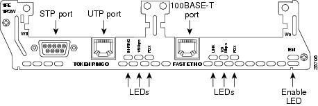
•1-Fast Ethernet 1-Token Ring 2-WAN card slot network module (NM-1FE1R2W and NM-1FE1R2W-V2). See Figure 13 for a sample faceplate.
Caution To comply with the Telcordia GR-1089 NEBS standard for electromagnetic compatibility and safety, connect the 1-Fast Ethernet 2-WAN card slot network modules (NM-1FE2W-V2, NM-1FE2W), the 2-Fast Ethernet 2-WAN card slot network modules (NM-2FE2W-V2, NM-2FE2W), the 2 WAN Card Slot Network Module (NM-2W)and the 1-Fast Ethernet 1-Token Ring 2-WAN card slot network modules (NM-1FE1R2W) only to intrabuilding or nonexposed wiring or cabling. The intrabuilding cable must be shielded and the shield must be grounded at both ends. The intra-building port(s) of the equipment or subassembly must not be metallically connected to interfaces that connect to the OSP or its wiring. These interfaces are designed for use as intra-building interfaces only (Type 2 or Type 4 ports as described in GR-1089-CORE, Issue 4) and require isolation from the exposed OSP cabling. The addition of Primary Protectors is not sufficient protection in order to connect these interfaces metallically to OSP wiring.
Figure 11 1-Fast Ethernet 2-WAN Card Slot Network Module
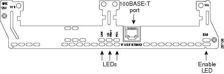
Figure 12 2-Fast Ethernet 2-WAN Card Slot Network Module
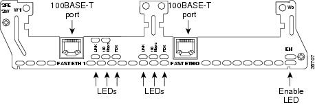
Figure 13 1-Fast Ethernet 1-Token Ring 2-WAN Card Slot Network Module
Проверка
В этом документе используется программное обеспечение коммутатора Cisco IOS версии 12.1(6)E. Описание всех выходных данных команд show version и show module см. в разделе Проверка синхронизации на коммутаторах Catalyst 6500/6000 с системным ПО Cisco IOS данного документа.
Так выглядит конфигурация после вступления в силу приведенных выше изменений.
Current configuration : 109 bytes
!
interface FastEthernet3/13
no ip address
switchport
switchport mode access
spanning-tree portfast
end
Надежный системный администратор для малого бизнеса
ежедневно, с 9:30 до 20:00 8 (499) 653-83-80
Ветрикс Надежный системный администратор для малого бизнеса
EtherChannel
На коммутаторах можно также включить функции EtherChannel, Fast EtherChannel (FEC) и Gigabit EtherChannel (GEC). Эти функции позволяют использовать несколько соединений между двумя одинаковыми устройствами как единое быстрое соединение с балансировкой нагрузки между соединениями. С помощью протокола PAgP коммутатор может автоматически формировать такие связи с соседним узлом. Порты коммутатора, на которых можно использовать протокол PAgP, обычно по умолчанию находятся в пассивном автоматическом режиме ( auto ). В режиме auto коммутаторы формируют единое соединение по запросу соседнего устройства. Если протокол используется в режиме auto , может возникнуть задержка порта до 15 секунд, прежде чем управление будет передано алгоритму STA. На порте протокол PAgP запускается раньше, чем протокол STP. На порте, подключенном к рабочей станции, нет необходимости использовать протокол PAgP. Если для данного порта коммутатора отключить режим PAgP (настройка off), такая задержка исключается.
Connecting Cisco Ethernet, Fast Ethernet, and Token Ring Network Modules to the Network
Проверка
Единственный способ проверить, что функция PortFast включена, это просмотреть конфигурацию. Помните, что порт Fast Ethernet должен сообщать, что режим PortFast включен. Для любого порта Ethernet режим PortFast включен, если в конфигурации порта не указано иное. Ниже представлен пример:
!
interface Ethernet 0/1
no spantree start-forwarding
!
interface Ethernet 0/2
!
!--- Output suppressed.
!
interface FastEthernet 0/26
spantree start-forwarding
!
В данной конфигурации можно видеть следующее.
Проще всего узнать состояние режима PortFast через систему меню. Если для параметра "Port Configuration" (Конфигурация порта) в главном меню выбрано значение (P) и порт, то в выходных данных отображается, включен ли режим "PortFast" (состояние enabled). Следующий пример выходных данных соответствует порту Fast Ethernet 0/26 (порт "А" на этом коммутаторе).
Catalyst 1900 - Port A Configuration
Built-in 100Base-FX
802.1d STP State: Blocking Forward Transitions: 0
----------------------- Settings ---------------------------------------
[D] Description/name of port
[S] Status of port Suspended-no-linkbeat
[I] Port priority (spanning tree) 128 (80 hex)
[C] Path cost (spanning tree) 10
[H] Port fast mode (spanning tree) Enabled
[E] Enhanced congestion control Disabled
[F] Full duplex / Flow control Half duplex
----------------------- Related Menus ----------------------------------
[A] Port addressing [V] View port statistics
[N] Next port [G] Goto port
[P] Previous port [X] Exit to Main Menu
Token Ring Network Modules
The following network modules provide Token Ring interfaces:
•1-port Ethernet 1-port Token Ring 2-WAN card slot module (NM-1E1R2W) (see Figure 20)
•1-port Fast Ethernet 1-port Token Ring 2-WAN card slot module (NM-1FE2R2W) (see Figure 21)
Figure 20 1-Ethernet 1-Token Ring 2-WAN Card Slot Network Module
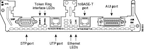
Figure 21 1-Fast Ethernet 1-Token Ring 2-WAN Card Slot Network Module
Согласование скорости и дуплексного режима
Обычно проблему задержки начального подключения можно решить, включив режим PortFast и отключив PAgP (если PAgP поддерживается). Если важна каждая секунда задержки, можно также задать скорость порта и дуплексный режим на коммутаторе вручную, если порт является многоскоростным (10/100 Мбит/с). Хотя автоматическое согласование и является полезной функцией, ее отключение на коммутаторах Catalyst 5500/5000 позволяет сэкономить 2 секунды. Автоматическое согласование не слишком полезно на коммутаторах Catalyst 2800 и Catalyst 2900XL.
Примечание: Если отключить автосогласование на коммутаторе, но оставить его активированным на рабочей станции, коммутатор не будет выполнять согласование с данным клиентом. Потенциально возможен случай, когда клиент не сможет выбрать такой же дуплексный режим, какой используется на коммутаторе. Дополнительные сведения о сложных моментах автоматического согласования см. в статье Настройка и устранение неполадок для автоматического согласования соединений Ethernet 10/100/1000 Мбит/с в полудуплексном и дуплексном режимах.
The documentation set for this product strives to use bias-free language. For the purposes of this documentation set, bias-free is defined as language that does not imply discrimination based on age, disability, gender, racial identity, ethnic identity, sexual orientation, socioeconomic status, and intersectionality. Exceptions may be present in the documentation due to language that is hardcoded in the user interfaces of the product software, language used based on RFP documentation, or language that is used by a referenced third-party product. Learn more about how Cisco is using Inclusive Language.
Configuring PortFast
The following sections describe how to configure PortFast on the switch.
Коммутатор Catalyst 1900/2800
В данном разделе рассматривается пример, в котором настраивается режим PortFast для порта Fast Ethernet. В примере используется программное обеспечение Enterprise Edition, версии 8. Коммутатор Catalyst 1900 автоматически сохраняет конфигурацию после внесения изменений в NVRAM. Помните, что не следует включать Portfast на порте, подключенном к другому коммутатору или концентратору. Режим PortFast требуется включать только для портов, подключенных к конечной станции. Помните, что аутсорсинг ИТ надо доверять только профессионалам.
Использование режима PortFast и других команд для устранения задержек соединения во время запуска рабочей станции. Часть 12
100BASE-T Connections
Use a two-pair Category 5 or unshielded twisted-pair (UTP) straight-through RJ-45 cable to connect a Fast Ethernet RJ-45 port to a switch, hub, repeater, server, or other network device. Figure 14 shows an RJ-45 port connected to a hub.
Note RJ-45 cables are not available from Cisco Systems. These cables are widely available and must be Category 5 cables.
Figure 14 Connecting a Fast Ethernet RJ-45 Port to a Hub

Fast Ethernet Network Modules
Fast Ethernet connections are provided on 1-port Fast Ethernet modules, and on 1-port Fast Ethernet, 2-port Fast Ethernet, and 1-port Fast Ethernet 1-port Token Ring 2-WAN card slot modules.
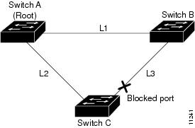
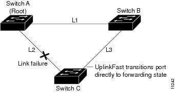
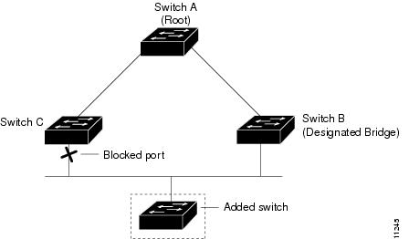
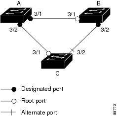
Understanding How UplinkFast Works
UplinkFast provides fast convergence using uplink groups in the network access layer after a spanning tree topology change. An uplink group is a set of ports (per VLAN), only one of which is forwarding at any given time. Specifically, an uplink group consists of the root port (which is forwarding) and a set of blocked ports (not including self-looped ports). The uplink group provides an alternate path in case the currently forwarding link fails.
As soon as the switch transitions the alternate port to the forwarding state, the switch begins transmitting dummy multicast frames on that port, one for each entry in the local Enhanced Address Recognition Logic (EARL) table (except those entries that are associated with the failed root port). By default, approximately 15 dummy multicast frames are transmitted per 100 ms.
Each dummy multicast frame uses the station address in the EARL table entry as its source MAC address and a dummy multicast address (01-00-0C-CD-CD-CD) as the destination MAC address.
Switches receiving these dummy multicast frames immediately update their EARL table entries for each source MAC address to use the new port, allowing the switches to begin using the new path almost immediately.
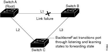
If connectivity on the original root port is restored, the switch waits for a period equal to twice the forward delay time plus 5 seconds before transitioning the port to the forwarding state. This situation allows the neighbor port enough time to transition through the listening and learning states to the forwarding state.
Token Ring LEDs
All network modules have an enable (EN) LED. The enable LED indicates that the module has passed its self-tests and is available to the router.
The 1-Ethernet 1-Token Ring 2-WAN card slot network module and the 1-Fast Ethernet 1-Token Ring 2-WAN card slot network module both have the following Token Ring LEDs:
•The 16MBPS LED indicates a ring speed of 16 Mbps. If it is off, the ring speed is 4 Mbps.
•The IN-RING LED indicates that the Token Ring interface is inserted into the ring. If it is off, the interface is not inserted into the ring.
The 1-Fast Ethernet 1-Token Ring 2-slot network module also has the FDX LED, which indicates full-duplex mode.
Timesaver When the IN-RING LED is off, you can unplug the Token Ring cable without causing a problem on the ring.
В данном разделе рассмотрены команды включения режима PortFast (STP) и отключения согласования режима магистрального соединения (DISL, DTP). В данной операционной системе протокол PAgP активизируется только после добавления порта к каналу EthernetChannel. Его не требуется отключать (off). Можно выполнить команду interface range , чтобы применить описанные команды сразу к целой группе портов. Команда interface range в данном примере позволяет применить описанные команды к портам 3/2 - 3/4 одновременно:
Примечание: Обратите внимание на наличие пробела между цифрой 2 и знаком - в команде interface range fastethernet 3/2 -4. Этот пробел требуется, чтобы избежать синтаксической ошибки.
В данном примере используется только один порт. Порт в программном обеспечении Cisco IOS по умолчанию является маршрутизируемым портом (уровень 3 [L3]), как в случае маршрутизатора. Данные команды необходимо применять только к портам, настроенным в качестве портов коммутатора (уровень 2 [L2]), так как эти порты используют протоколы второго уровня, такие как STP или DTP, и, как следствие, подвержены задержкам при запуске рабочих станций, которые как правило передают на ИТ аутсорсинг. Чтобы сделать маршрутизируемый порт портом коммутатора, выполните команду switchport (без параметров) в режиме интерфейса.
Connecting Token Ring Ports
The 1-Ethernet 1-Token Ring 2-WAN card slot network module and the 1-Fast Ethernet 1-Token Ring 2-WAN card slot network module each have one DB-9 connector for an STP Token Ring connection and one RJ-45 connector for a UTP Token Ring connection. Only one connector can be active at a time.
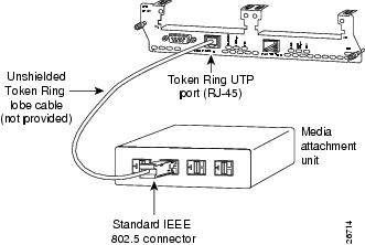
To connect the module to a Token Ring network, attach one end of a shielded Token Ring lobe cable to the DB-9 connector on the network module (see Figure 22), or attach one end of an unshielded Token Ring lobe cable to the UTP connector on the network module (see Figure 23). Attach the other end of the cable to the Token Ring media attachment unit (MAU). The network module automatically detects which connector is in use.
Figure 22 Connecting a Token Ring STP Port (DB-9) to a MAU
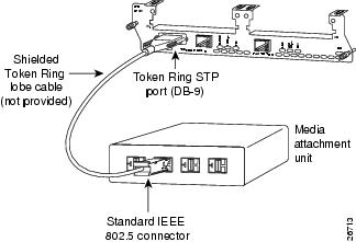
Figure 23 Connecting a Token Ring UTP Port (RJ-45) to an MAU
Connecting Ethernet Ports
If an Ethernet port offers both an AUI connector and a 10BASE-T connector, you can use either connector, but not both at the same time.
Table Of Contents
Ethernet 2-WAN Card Slot Modules
The following 2-slot network modules provide one or two Ethernet interfaces, plus two slots for optional WAN interface cards:
•1-Ethernet 2-WAN card slot network module (NM-1E2W) (see Figure 3)
•2-Ethernet 2-WAN card slot network module (NM-2E2W) (see Figure 4)
•1-Ethernet 1-Token Ring 2-WAN card slot network module (NM-1E1R2W) (see Figure 5)
Figure 3 1-Ethernet 2-WAN Card Slot Network Module
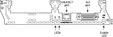
Figure 4 2-Ethernet 2-WAN Card Slot Network Module
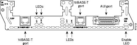
Figure 5 1-Ethernet 1-Token Ring 2-WAN Card Slot Network Module
100BASE-FX Connections
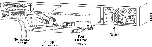
Attach a multimode fiber-optic cable with SC-type connectors directly to the port on the Fast Ethernet network module (remove the protective plug from the port if it is present). Use either one duplex SC connector (see Figure 15 and Figure 17) or two simplex SC connectors (see Figure 16 and Figure 18). Attach the other end of the cable to a repeater, hub, or wall outlet. Be sure to observe the correct relationship between the receive (RX) and transmit (TX) ports on the network module and the cable.
Note Multimode SC-type fiber-optic cables are widely available commercially. Cisco Systems does not supply these cables.
Figure 15 Duplex SC Connector
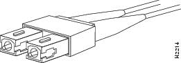
Figure 16 Simplex SC Connector
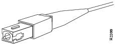
Figure 17 Connecting a Fast Ethernet FX Port to a Repeater or Hub (Duplex Connector)
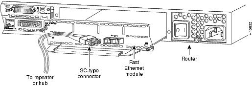
Figure 18 Connecting a Fast Ethernet FX Port to a Repeater or Hub (Simplex Connectors)
Enabling PortFast on an Access Port
Caution You can use PortFast to connect a single end station or a switch port to a switch port. If you enable PortFast on a port that is connected to another Layer 2 device, such as a switch, you might create network loops.
To enable PortFast on a switch port, perform this task in privileged mode:
This example shows how to enable PortFast on port 1 of module 4 and verify the configuration (the PortFast status is shown in the "Fast-Start" column):
AUI Connections
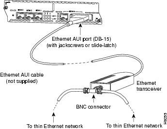
Use an Ethernet AUI cable to connect an AUI port to an Ethernet transceiver. These ports are color-coded yellow. The female end of the AUI cable mates with the slide-latch connector of the transceiver cable. Figure 6 shows a thin Ethernet transceiver as an example, but you can use any type of Ethernet transceiver.
If the transceiver cable has thumbscrew connectors, you can connect it directly to the AUI port by replacing the AUI port slide latch with a jackscrew (provided in a separate bag).
Figure 6 Connecting an Ethernet AUI Port to a Transceiver
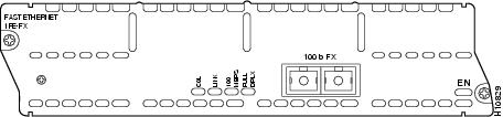
1-Port Fast Ethernet Modules
The following network modules provide Fast Ethernet interfaces:
•1-port Fast Ethernet network module with TX connector, Cisco product number NM-1FE-TX. (See Figure 9.) This module provides an RJ-45 connector for direct connection to 100BASE-T Ethernet networks.
•1-port Fast Ethernet network module with FX connector, Cisco product number NM-1FE-FX. (See Figure 10.) This module provides a duplex SC-type fiber-optic port for direct connection to 100BASE-FX Ethernet networks.
Figure 9 1-Port Fast Ethernet Network Module (TX Connector)
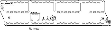
Figure 10 1-Port Fast Ethernet Network Module (FX Connector)
Understanding How BackboneFast Works
Конфигурация
Начните с порта в состоянии по умолчанию (L3) и выполните следующие действия.
1. Выполните команду switchport , чтобы настроить порт в качестве порта коммутатора.
Примечание: Выполните данную команду, введя ее в отдельной строке.
2. Чтобы отключить протокол DTP (off), настройте порт только в качестве порта доступа.
3. Включите функцию PortFast протокола STP.
4. Сохраните конфигурацию.
Команда show run interface fastethernet 3/13 в данном примере показывает текущую конфигурацию данного порта:
Current configuration : 61 bytes
!
interface FastEthernet3/13
no ip address
shutdown
end
Configuring Spanning Tree PortFast, BPDU Guard, BPDU Filter, UplinkFast, BackboneFast, and Loop Guard
This chapter describes how to configure the PortFast, BPDU guard, BPDU filter, UplinkFast, BackboneFast, and loop guard spanning tree enhancements on the Catalyst enterprise LAN switches.
Note For information on configuring spanning tree, see Chapter 7, "Configuring Spanning Tree."
Ethernet LEDs
This section describes Ethernet module LEDs. Figure 8 shows 4-port Ethernet network module LEDs as an example.
All network modules have an enable (EN) LED. This LED indicates that the module has passed its self-tests and is available to the router.
Each Ethernet port has two LEDs. The activity (ACT) LED indicates that the router is sending or receiving Ethernet transmissions. The link (LINK) LED indicates that the Ethernet port is receiving the link integrity signal from the hub (10BASE-T only).
Figure 8 Ethernet Network Module LEDs (Typical)
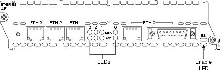
Table Of Contents
Connecting Fast Ethernet Ports
Use the following sections for 100BASE-T or 100BASE-FX connections.
Ethernet Connectors
The 1-port Ethernet network module, the 1-Ethernet 2-slot network module, and the 1-Ethernet 1-Token Ring 2-slot network module each provide a single Ethernet port. This port uses either the attachment unit interface (AUI) DB-15 connector on the right side of the module or the 10BASE-T (RJ-45) connector next to it. Only one of these connectors can be active at a time. The active port is identified in software by port type (Ethernet), slot number on the module, and port number 0.
All modules detect the type of network connection automatically, and you do not need to choose the media type in software. If cables are plugged into both ports, the 10BASE-T connection is chosen.
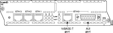
The 4-port Ethernet network module has ports for four Ethernet connections (0, 1, 2, and 3). Port 0 offers a choice of an AUI or 10BASE-T interface. Ethernet ports 1, 2, and 3 use 10BASE-T connectors only. These ports do not provide an AUI connector.
The 2-Ethernet 2-slot network module has ports for two Ethernet connections. Port 0 offers a choice of AUI or 10BASE-T. Port 1 uses 10BASE-T only.
Understanding How PortFast BPDU Filtering Works
BPDU filtering allows you to avoid transmitting BPDUs on PortFast-enabled ports that are connected to an end system. When you enable PortFast on the switch, spanning tree places ports in the forwarding state immediately, instead of going through the listening, learning, and forwarding states.
By default, spanning tree sends BPDUs from all ports regardless of whether PortFast is enabled. BDPU filtering is on a per-switch basis; after you enable BPDU filtering, it applies to all PortFast-enabled ports on the switch.
Конфигурация
Режим магистрального соединения
В коммутаторах имеется также возможность формирования для порта магистрального соединения. Магистральное соединение настраивается между двумя устройствами, когда через них передается трафик из нескольких сетей VLAN. Сеть VLAN — это создаваемая коммутаторами сеть, в которой группа рабочих станций объединена в единый сегмент или домен широковещательной рассылки. Благодаря магистральным портам такие сети VLAN могут включать в себя несколько коммутаторов, благодаря чему одна сеть VLAN может охватить всю корпоративную среду. Для такого расширения сетей VLAN магистральные порты добавляют к пакетам теги, в которых указывается, к какой сети VLAN принадлежит пакет.
Существуют различные типы протоколов магистрального соединения. Если порт может стать магистральным, возможно, этот порт может формировать магистральные соединения автоматически. В некоторых случаях порт может даже согласовывать тип магистрального соединения, которое будет использоваться на этом порту. Возможность согласования метода магистрального соединения с другим устройством обеспечивается протоколом DTP. Предшественником протокола DTP является протокол DISL (Dynamic Inter-Switch Link Protocol). Использование этих протоколов может вызвать задержки при запуске порта на коммутаторе.
Обычно порт, подключенный к рабочей станции, принадлежит только к одной сети VLAN. Поэтому такому порту не требуется режим магистрального соединения. Если порт способен согласовывать формирование магистрального соединения, обычно он по умолчанию функционирует в автоматическом режиме (auto). Отключив режим магистрального соединения порта (настройка off), можно еще больше уменьшить время задержки при запуске порта коммутатора.
Общие сведения
В этом разделе описываются четыре функции некоторых типов коммутаторов, вызывающие начальную задержку при подключении устройства к коммутатору. Рабочая станция обычно не вызывает образования петель STP или не нуждается в подобной функции (обычно PAgP и/или DTP), поэтому необходимости в такой задержке нет. Протокол STP Если вы недавно перешли от среды на базе концентраторов к среде коммутаторов, могут возникать задержки подключения при запуске рабочих станций, обусловленные существенными различиями в работе концентратора и коммутатора. Коммутатор обеспечивает подключение на канальном уровне, а не на физическом уровне. Коммутатор с помощью алгоритма ретрансляции определяет, нужно ли передавать пакеты, полученные на одном порте, через другие порты. Алгоритм ретрансляции чувствителен к наличию физических петель в сетевой топологии. Из-за этой чувствительности на коммутаторах используется протокол STP, который устраняет петли в топологии. При использовании протокола STP все задействованные в этом процессе порты становятся активными значительно медленнее, чем обычно, так как STP выполняет обнаружение и блокировку петель. Без STP сеть с мостовыми соединениями, в которой есть физические петли, работать не будет. Несмотря на задержки, связанные с этим процессом, протокол STP весьма полезен. Протокол STP, используемый на коммутаторах Catalyst, соответствует отраслевому стандарту (IEEE 802.1D). Тщательно продумайте переход на ит аутсорсинг и не думайте об этой проблеме.
После подключения порта коммутатора и включения его в группу мостов запускается протокол STP для данного порта. Порт, на котором используется протокол STP, может быть в одном из следующих пяти состояний:
- блокировка (blocking)
- прослушивание (listening)
- самообучение (learning)
- пересылка (forwarding)
- отключен (disabled)
По правилам протокола STP порт сначала переходит в состояние блокировки , а затем сразу проходит через состояния прослушивания и самообучения . По умолчанию порт находится в состоянии прослушивания около 15 секунд и в состоянии самообучения также 15 секунд. В состоянии прослушивания коммутатор пытается определить место порта в топологии STP. Коммутатору крайне важно определить, является ли порт частью физической петли. Если порт является частью петли, он может быть выбран для перехода в режим блокировки . В режиме блокировки порт не отправляет и не получает данные пользователя, чтобы исключить возникновение петли. Если порт не является частью петли, он переходит в состояние самообучения , в котором определяются используемые с данным портом MAC-адреса. Процесс инициализации STP занимает около 30 секунд.
Если к порту коммутатора подключена рабочая станция, сервер с одной сетевой интерфесной платой или IP-телефон, то такое соединение не может образовать физической петли. Такие соединения считаются листовыми узлами. Если подключение рабочей станции не может вызвать образование петли, нет смысла ждать 30 секунд, пока коммутатор проверяет сеть на наличие петель. Для этого корпорация Cisco разработала функцию PortFast (или функцию быстрого запуска). Если эта функция используется для какого-либо порта, протокол STP считает, что этот порт не является частью петли, и немедленно переводит его в состояние пересылки , минуя состояния блокировки, прослушивания и самообучения. Эта команда не отключает протокол STP. При выполнении этой команды протокол STP пропускает несколько начальных этапов (в которых в данной ситуации нет необходимости) на выбранном порте.
caution Предостережение: Никогда не используйте функцию PortFast на портах коммутатора, подключенных к другим коммутаторам, концентраторам или маршрутизаторам. Такие соединения могут образовывать физические петли, поэтому в этих случаях процедура инициализации STP должна выполняться полностью. Петля в дереве STP может вывести сеть из строя. И поэтому обслуживание компьютеров надо передовать специалистам. Если включить функцию PortFast для порта, являющегося частью физической петли, может возникнуть ситуация, когда пакеты будут пересылаться (и даже могут умножаться) таким образом, что сеть не сможет восстановиться.
Проверка синхронизации на Catalyst 1900
Значения синхронизации трудно проверять на коммутаторе Catalyst 1900/2820 из-за недостатка средств отладки. Выполните следующие действия.
1. Отправьте эхо-запросы к данному коммутатору с подключенного к нему ПК.
2. Отключите кабель от коммутатора.
3. Снова подключите кабель и запишите период времени до момента ответа коммутатора на эхо-запрос.
Выполните данную процедуру при включенном и выключенном режиме PortFast. В случае порта Ethernet с включенным режимом PortFast (состояние по умолчанию) ПК получает ответ через 5-6 секунд. При выключенном режиме PortFast ПК получает ответ через 34-35 секунд.
Understanding How Loop Guard Works
Unidirectional link failures may cause a root port or alternate port to become designated as root if BPDUs are absent. Some software failures may introduce temporary loops in the network. Loop guard checks if a root port or an alternate root port receives BPDUs. If the port is receiving BPDUs, loop guard puts the port into an inconsistent state until it starts receiving BPDUs again. Loop guard isolates the failure and lets spanning tree converge to a stable topology without the failed link or bridge.
You can enable loop guard per port with the set spantree guard loop command.
Note We recommend that you enable loop guard on root ports and alternate root ports on access switches.
Loop guard interacts with other features as follows:
•Loop guard does not affect the functionality of UplinkFast or BackboneFast.
•Root guard forces a port to always be designated as the root port. Loop guard is effective only if the port is a root port or an alternate port. Do not enable loop guard and root guard on a port at the same time.
•PortFast transitions a port into a forwarding state immediately when a link is established. Because a PortFast-enabled port will not be a root port or alternate port, loop guard and PortFast cannot be configured on the same port. Assigning dynamic VLAN membership for the port requires that the port is PortFast enabled. Do not configure a loop guard-enabled port with dynamic VLAN membership.
•If your network has a type-inconsistent port or a PVID-inconsistent port, all BPDUs are dropped until the misconfiguration is corrected. The port transitions out of the inconsistent state after the message age expires. Loop guard ignores the message age expiration on type-inconsistent ports and PVID-inconsistent ports. If the port is already blocked by loop guard, misconfigured BPDUs that are received on the port make loop guard recover, but the port is moved into the type-inconsistent state or PVID-inconsistent state.
•In high-availability switch configurations, if a port is put into the blocked state by loop guard, it remains blocked even after a switchover to the redundant supervisor engine. The newly activated supervisor engine recovers the port only after receiving a BPDU on that port.
•Loop guard uses the ports known to spanning tree. Loop guard can take advantage of logical ports provided by the Port Aggregation Protocol (PAgP). However, to form a channel, all the physical ports grouped in the channel must have compatible configurations. PAgP enforces uniform configurations of root guard or loop guard on all the physical ports to form a channel.
These caveats apply to loop guard:
–Spanning tree always chooses the first operational port in the channel to send the BPDUs. If that link becomes unidirectional, loop guard blocks the channel, even if other links in the channel are functioning properly.
–If a set of ports that are already blocked by loop guard are grouped together to form a channel, spanning tree loses all the state information for those ports and the new channel port may obtain the forwarding state with a designated role.
–If a channel is blocked by loop guard and the channel breaks, spanning tree loses all the state information. The individual physical ports may obtain the forwarding state with the designated role, even if one or more of the links that formed the channel are unidirectional.
•You can enable UniDirectional Link Detection (UDLD) to help isolate the link failure. A loop may occur until UDLD detects the failure, but loop guard will not be able to detect it.
•Loop guard has no effect on a disabled spanning tree instance or a VLAN.
1- and 4-Port Ethernet Modules
The following network modules provide Ethernet interfaces:
•1-port Ethernet network module (NM-1E) (see Figure 1)
•4-port Ethernet network module (NM-4E) (see Figure 2)
Figure 1 1-Port Ethernet Network Module
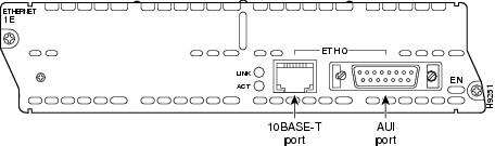
Figure 2 4-Port Ethernet Network Module
10BASE-T Connections
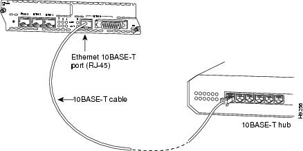
Use an Ethernet 10BASE-T cable to connect a 10BASE-T port to a hub or other network device. These ports are color-coded yellow. Figure 7 shows the 10BASE-T port on an Ethernet network module connected to a hub.
Figure 7 Connecting an Ethernet 10BASE-T Port to a Hub
Understanding How PortFast Works
PortFast causes a switch or trunk port to enter the spanning tree forwarding state immediately, bypassing the listening and learning states.
You can use PortFast on switch or trunk ports that are connected to a single workstation, switch, or server to allow those devices to connect to the network immediately, instead of waiting for the port to transition from the listening and learning states to the forwarding state.
Caution You can use PortFast to connect a single end station or a switch port to a switch port. If you enable PortFast on a port that is connected to another Layer 2 device, such as a switch, you might create network loops.
When the switch powers up, or when a device is connected to a port, the port enters the spanning tree listening state. When the Forward Delay timer expires, the port enters the learning state. When the Forward Delay timer expires a second time, the port is transitioned to the forwarding or blocking state.
When you enable PortFast on a switch or trunk port, the port is immediately transitioned to the spanning tree forwarding state.
Fast Ethernet LEDs
This section describes Fast Ethernet module LEDs. Figure 19 shows 1-port Fast Ethernet network module LEDs as an example.
Figure 19 1-Port Fast Ethernet Network Module LEDs
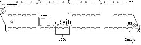
All network modules have an enable (EN) LED. The enable LED indicates that the module has passed its self-tests and is available to the router.
Fast Ethernet network modules have the additional LEDs shown in Table 1.
Ethernet Network Modules
Ethernet connections are provided on 1- and 4-port Ethernet modules, and on 1-port Ethernet, 2-port Ethernet, and 1-port Ethernet 1-port Token Ring 2-WAN card slot modules.
Дополнительное преимущество режима PortFast
Есть другое связанное с протоколом STP преимущество использования режима PortFast в своей сети. Всякий раз, когда канал становится активным и переходит в STP-состояние пересылки, коммутатор отправляет специальное STP-уведомление об изменении топологии (TCN). Обслуживание компьютеров - вид деятельности организаций, знающих преимущества решения PortFast. TCN-пакет доходит до корня дерева STP, откуда данный TCN-пакет распространяется на все коммутаторы в данной сети VLAN. После этого все коммутаторы объявляют свои таблицы MAC-адресов устаревшими из-за параметра задержки пересылки (forward delay), которому обычно задается значение 15 секунд. Итак, при каждом присоединении рабочей станции к группе мостов, MAC-адреса на всех коммутаторах устаревают через 15 секунд вместо обычных 300 секунд.
Активизация рабочей станции не приводит к значительным изменениям топологии. Не требуется, чтобы все коммутаторы в данной сети VLAN проходили через период быстрого устаревания TCN-пакетов. Если режим PortFast включен, коммутатор не передает TCN-пакеты, когда порт становится активным. Если вам интересно как заблокировать сайт, то необходимо прочесть соответствующую статью.
Общие сведения
Протокол STP EtherChannel
Режим магистрального соединения
Согласование скорости и дуплексного режима
Читайте также: