
Port binding vmware что это
When I first started really getting in to multipath iSCSI for vSphere, I had two major hurdles that really took a lot of time and research to figure out before deploying.
- How to configure a vSphere Distributed Switch for iSCSI multipath MPIO with each path being on different subnets (a.k.a. each interface on separate subnets)
So many articles on the internet, and most were wrong.
In this article I’ll be getting in to the first point, how to configure a vSphere Distributed Switch for iSCSI multipath MPIO with multiple subnets. You can find information on the second point here, when to use iSCSI Port Binding, and why.
I’ll start off by saying that when using multiple subnets on multiple isolated networks for SAN connectivity, you DO NOT use iSCSI Port Binding.
Jumbo Frames
There is one additional step if you are using jumbo frames. Please note that to use jumbo frames, all NICs, physical switches, and the storage device itself need to be configured to support this. On the VMWare side of things, you need to apply the following settings:
When you configure networking with software iSCSI, consider several best practices.
Routing with Software iSCSI
You can use the esxcli command to add static routes for your iSCSI traffic. After you configure static routes, initiator and target ports in different subnets can communicate with each other.
Example 1. Using static routes with port binding
In this example, you keep all bound vmkernel ports in one subnet (N1) and configure all target portals in another subnet (N2). You can then add a static route for the target subnet (N2).
Use the following command:
Example 2. Using static routes to create multiple paths
In this configuration, you use static routing when using different subnets. You cannot use the port binding with this configuration.

You configure vmk1 and vmk2 in separate subnets, 192.168.1.0 and 192.168.2.0. Your target portals are also in separate subnets, 10.115.155.0 and 10.155.179.0.
You can add the static route for 10.115.155.0 from vmk1. Make sure that the gateway is reachable from vmk1.
You then add static route for 10.115.179.0 from vmk2. Make sure that the gateway is reachable from vmk2.
When connecting with Port 0 of Controller A, vmk1 is used.
When connecting with Port 0 of Controller B, vmk2 is used.
Example 3. Routing with a separate gateway per vmkernel port
Starting with vSphere 6.5, you can configure a separate gateway per VMkernel port. If you use DHCP to obtain IP configuration for a VMkernel port, gateway information can also be obtained using DHCP.
To see gateway information per VMkernel port, use the following command:
With separate gateways per VMkernel port, you use port binding to reach targets in different subnets.

14.02.2012

itpro

VMWare

Комментариев пока нет
Одним из улучшений, появившихся в vSphere 5 – является возможность привязки (в англоязычной документации это термин bind, binding) iSCSI портов к интерфейсу VMkernel через графический интерфейс консоли vSphere.
Для тех, кто не помнит, зачем вообще нужна это фича, напомню, что привязка iSCSI к порту VMkernel позволяет создать отказоустойчивую среду iSCSI с функциями балансировкой нагрузки (мультипассинг).
Как вы, вероятно, помните в предыдущей версии vSphere 4.1 выполнить это действие можно только с помощью командной строки (CLI), например такой:
Настройка привязки iSCSI портов осуществляется из окна свойств программного iSCSI адаптора (раздел Storage Adapters — > выбираем интересующий нас адаптер -> Properties ->вкладка Network Configuration).

The selected physical network adapter is not associated with a vmkernel with complaint teaming and failover policy.

Поэтому вы должны будете создать 1 или 2 отдельные группы портов VMkernel каждая из которых имеет отдельную физическую сетевую карты и затем привязать каждую из этих групп к iSCSI адаптеру. Все остальные адаптеры на виртуальном коммутаторе vSwitch должны быть помечены как «unused».

После того, как мы сделали 2 интерфейса vMkernel, их можно привязать к адаптеру. Еще раз переходим на вкладку свойств iSCSI адаптора и видим, что у нас появилась возможность выбрать и добавить группу портов vMkernel.

Как вы видите, одна группа уже добавлена

И нам осталось добавить вторую.
И, наконец, оба порта VMKernel привязаны к интерфейсу iSCSI.

После того, как вы закроете окно настройки, не забудьте выполнить рескан.
Port Groups are the group of ports used on that port group. Port Groups are created on the Virtual Switch then VM’s are assigned to the Port Group. Port Groups are also used to manage the vm by categories such as Windows, Linux etc. You can create multiple port groups depending on your requirements. In vSwitch you can assign policies on vSwitch & the Port group level but in case of vDS you will have the more granular option by which you can assign policies on ports also. In this post we will look at some of the Basic Port group settings which you will get while creating port group on the vSphere Distributed Switch.
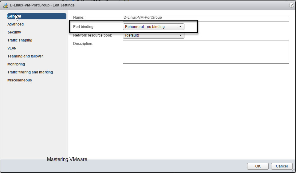
When you create new port group or edit an existing port group you will find the common general settings which allows a simple operations such as port group name, number of ports required etc etc. You can check the below image for more.

Here you can configure the Port binding settings as well as the Port allocation settings. You can also set the Number of ports you want to use with this port group. So we will look at each of the Port Group settings one by one.
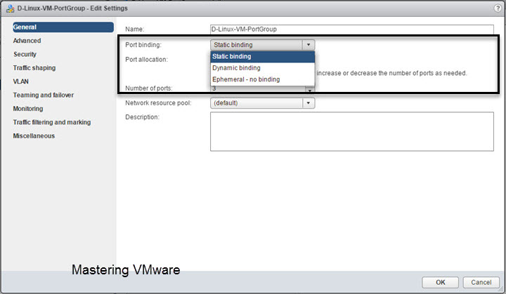
Port binding:
Port binding has 3 options Static binding, Dynamic binding & Ephemeral – no binding.
Port allocation :
Port allocation will give you the 2 option either you can go for Fixed Port allocation or you can choose the Elastic Port allocation.

Static Binding:
When you choose the Static binding you can choose for either Fixed Port allocation or Elastic Port allocation.
Now we will see on how Port allocation works with Static binding
Static Binding with Fixed Port allocation:
Static binding as the name says port are allocated static at the time of creation only.
First we will see on Static Port binding with Fixed Port allocation option.


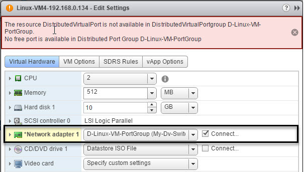
In Static port binding with Fixed port allocation you specify the ports you want to use with Port Group. So let’s say you have specified 3 ports in the Number of ports to be used. So now you can only use the 3 Port in this port group. If you try to assign new vm to this port group you will get the error message saying that “No free Port is available”.
I have also attached screenshot of the error below.
Static binding with Elastic Port allocation:
In this scenario Static binding with Elastic port allocation Port numbers will be elastically increased or decreased depending on the number of ports needed.
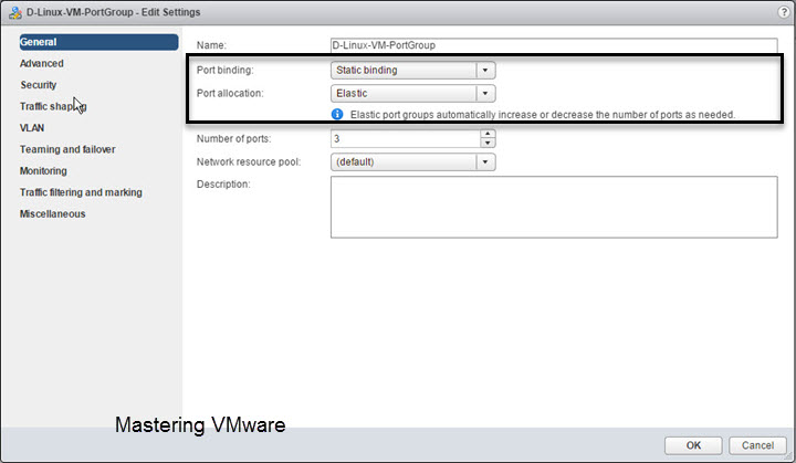
In this scenario if all the ports are used by the virtual machines and we add the new vm to this port group then vDS will automatically increase the number of ports required but when we remove or delete the vm from this port group then Port Numbers will get reduced to the ports which are specified at the time of creation of port group.
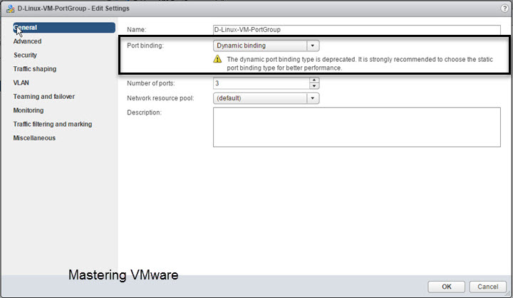
Dynamic Binding :
VMware has deprecated the Dynamic port binding so it is strongly recommended to not to choose Dynamic binding instead you can go for static binding with elastic port allocation.
Ephemeral – no binding:
When you choose the Ephemeral – no binding you will see that Number of ports option is not there. It is because Ephemeral port binding works with like the standard switch & uses all the ports available.
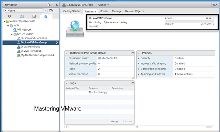
When you choose Ephemeral – no binding you will see that Ports are set to zero at first.
When you assign the powered on vm to this port group you can see that the Ports are increased & Ports are showing 2 used ports.

But when the VM is powered off you can see that the Ports value is decreased to 1 but Virtual Machines connected is still the 2.
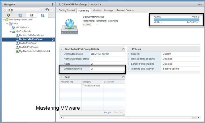
So Ephemeral – no binding increase or decrease the port values based on the VM when it is powered on & connected to the vDS.
That’s it for Today Friends. I Hope you liked reading this post & If you find anything more to be added or removed feel free to write it in our comments. If you find it useful You are Feel free to share this on social media to help others & spread knowledge.
If you have any query on any thing you are free to write it in our comments section & we will make sure to provide you the better solution as soon as possible.
Join Our LinkedIn Group to get Updates & Discussions : Mastering VMware.
Checkout our Facebook Group for discussions & more.
You can also Like & Share our Facebook Page for Latest Updates.
Port Groups are the group of ports used on that port group. Port Groups are created on the Virtual Switch then VM’s are assigned to the Port Group. Port Groups are also used to manage the vm by categories such as Windows, Linux etc. You can create multiple port groups depending on your requirements. In vSwitch you can assign policies on vSwitch & the Port group level but in case of vDS you will have the more granular option by which you can assign policies on ports also. In this post we will look at some of the advanced Port group settings which you will get for additional security & networking.
When using the Distributed Switch you can configure the Advanced port group settings based on the per port policies which helps in better & efficient management of networking & also provides the additional security to the virtual networks.
When you create port group or if you have already created port group. Go to Edit settings > Advanced.
Here you can find some of the Advanced settings available for the Port group. Some of the settings are exclusive only to the distributed switch not available in Standard Switch.
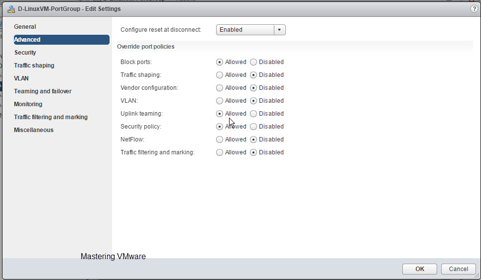
Configure reset at disconnect:
If you Enable this per-port overrides settings will be discarded. When a distributed port is disconnected from a virtual machine, the configuration of the distributed port is reset to the distributed port group setting.
Override Port Policies:
Here you can override the Policies on the per port level if you want. You just have to choose Allowed or Disabled. Let’s see what each option will do for you.
Block ports:
It will help you to Block specific ports from sending & receiving the network traffic from Distributed Switch. This option is not available in the Standard Switch.
Traffic Shaping:
As you can easily understand by it’s name what it does but there comes a some advantage using with distributed switch. So when this is allowed in the distributed switch port group you can restrict the network bandwidth on the port group from incoming & outgoing traffic. In case you are using standard switch you can only restrict the outgoing traffic.
VLAN:
It will allow you to configure the VLAN Tagging on per port level in the Distributed Switch. You can configure External Switch Tagging(EST), Virtual Switch Tagging (VST), and Virtual Guest Tagging (VGT).
Uplink Teaming:
It will allow you to Teaming the Uplinks per port group for the Load balancing & Failover.
Security Policy:
Provides protection of traffic against MAC address impersonation and unwanted port scanning. The networking security policy is implemented in Layer 2 of the networking protocol stack.
NetFlow:
NetFlow is network analysis tool which help you to analyze virtual machine IP traffic that flows through distributed switch port group. NetFlow is available on a vSphere Distributed Switch version 5.0.0 and later. Version 5.1 and later of the switch supports IPFIX (NetFlow version 10). This option is not available in the Standard Switch.
Traffic Filtering & Marking:
By using the traffic filtering and marking policy, you can protect the virtual network from unwanted traffic and security attacks or apply a QoS tag to a certain type of traffic. The traffic filtering and marking policy represents an ordered set of network traffic rules for security and for QoS tagging of the data flow through the ports of a distributed switch. In general, a rule consists of a qualifier for traffic, and of an action for restricting or prioritizing the matching traffic. This option is not available in the Standard Switch.
That’s it for Today Friends. I Hope you liked reading this post & If you find anything more to be added or removed feel free to write it in our comments. If you find it useful You are Feel free to share this on social media to help others & spread knowledge.
If you have any query on any thing you are free to write it in our comments section & we will make sure to provide you the better solution as soon as possible.
Join Our LinkedIn Group to get Updates & Discussions : Mastering VMware.
Checkout our Facebook Group for discussions & more.
You can also Like & Share our Facebook Page for Latest Updates.
The setup
My configuration consists of two hosts connecting to an iSCSI device over 3 different paths, each with it’s own subnet. Each host has multiple NICs, and the storage device has multiple NICs as well.
As always, I plan the deployment on paper before touching anything. When getting ready for deployment, you should write down:
- Which subnets you will use
- Choose IP addresses for your SAN and hosts
- I always draw a map that explains what’s connecting to what. When you start rolling this out, it’s good to have that image in your mind and on paper. If you lose track it helps to get back on track and avoid mistakes.
For this example, let’s assume that we have 3 connections (I know it’s an odd number):
Subnets to be used:
SAN Device IP Assignment:
- 10.0.1.1 (NIC 1)
- 10.0.2.1 (NIC 2)
- 10.0.3.1 (NIC 3)
Host 1 IP Assignment:
- 10.0.1.2 (NIC 1)
- 10.0.2.2 (NIC 2)
- 10.0.3.2 (Nic 3)
Host 2 IP Assignment:
- 10.0.1.3 (NIC 1)
- 10.0.2.3 (NIC 2)
- 10.0.3.3 (NIC 3)
So no we know where everything is going to sit, and it’s addresses. It’s now time to configure a vSphere Distributed Switch and roll it out to the hosts.
Software iSCSI Port Binding
You can bind the software iSCSI initiator on the ESXi host to a single or multiple VMkernel ports, so that iSCSI traffic flows only through the bound ports. When port binding is configured, the iSCSI initiator creates iSCSI sessions from all bound ports to all configured target portals.
See the following examples.| VMkernel Ports | Target Portals | iSCSI Sessions |
|---|---|---|
| 2 bound VMkernel ports | 2 target portals | 4 sessions (2 x 2) |
| 4 bound VMkernel ports | 1 target portal | 4 sessions (4 x 1) |
| 2 bound VMkernel ports | 4 target portals | 8 sessions (2 x 4) |
Note: Make sure that all target portals are reachable from all VMkernel ports when port binding is used. Otherwise, iSCSI sessions might fail to create. As a result, the rescan operation might take longer than expected.
No Port Binding
If you do not use port binding, the ESXi networking layer selects the best VMkernel port based on its routing table. The host uses the port to create an iSCSI session with the target portal. Without the port binding, only one session per each target portal is created.
See the following examples.| VMkernel Ports | Target Portals | iSCSI Sessions |
|---|---|---|
| 2 unbound VMkernel ports | 2 target portals | 2 sessions |
| 4 unbound VMkernel ports | 1 target portal | 1 session |
| 2 unbound VMkernel ports | 4 target portals | 4 sessions |
Instructions
- We’ll start off by going in to the vSphere client and creating a new vSphere Distributed Switch. You can name this switch whatever you want, I’ll use “iSCSI-vDS” for this example. Going through the wizard you can assign a name. Stop when you get to “Add Hosts and Physical Adapter”, on this page we will chose “Add Later”. Also, when it asks us to create a default port group, we will un-check the box and NOT create one.
- Now we need to create some “Port Groups”. Essentially we will be creating a Port Group for each subnet and NIC for the storage configuration. In this example case, we have 3 subnets, and 3 NICs per host, so we will be creating 3 port groups. Go ahead and right click on the new vSphere distributed switch we created (“iSCSI-vDS” in my example), and create a new port group. I’ll be naming my first one “iSCSI-01”, second will be called “iSCSI-02”, and so on. You can go ahead and create one for each subnet. After these are created, we’ll end up with this:
- After we have this setup, we now need to do some VERY important configuration. As of right now by default, each port group will have all uplinks configured as Active which we DO NOT want. Essentially what we will be doing, is assigning only one Active Uplink per Port Group. Each port group will be on it’s own subnet, so we need to make sure that the applicable uplink is only active, and the remainder are thrown in to the “Unused Uplinks” section. This can be achieved by right clicking on each port group, and going to “Teaming and Failover” underneath “Policies”. You’ll need to select the applicable uplinks and using the “Move Down” button, move them down to “Unused Uplinks”. Below you’ll see some screenshots from the iSCSI-02, and iSCSI-03 port groups we’ve created in this example:
You’ll notice that the iSCSI-02 port group, only has the iSCSI-02 uplink marked as active. Also, the iSCSI-03 port group, only have the iSCSI-03 uplink marked as active. The same applies to iSCSI-01, and any other links you have (more if you have more links). Please ignore the entry for “iSCSI-04”, I created this for something else, pretend the entry isn’t there. If you do have 4 subnets, and 4 NICs, then you would have a 4th port group. - Now we need to add the vSphere Distributed Switches to the hosts. Right click on the “iSCSI-vDS” Distributed switch we created and select “Add Host”. Select ONLY the hosts, and DO NOT select any of the physical adapters. A box will appear mentioning you haven’t selected any physical adapters, simply hit “Yes” to “Do you want to continue adding the hosts”. For the rest of the wizard just keep hitting “Next”, we don’t need to change anything. Example below:
So here we are now, we have a vSphere Distributed Switch created, we have the port groups created, we’ve configured the port groups, and the vDS is attached to our hosts… Now we need to create vmks (vmkernel interfaces) in each port group, and then attach physical adapters to the port groups. - Head over to the Configuration tab inside of your ESXi host, and go to “Networking”. You’ll notice the newly created vSphere Distributed Switch is now inside the window. Expand it. You’ll need to perform these steps on each of your ESXi hosts. Essentially what we are doing, is creating a vmk on each port group, on each host. Click on “Manage Virtual Adapters” and click on “Add”. We’ll select “New Virtual Adapter”, then on the next screen our only option will be “VMKernel”, click Next. In the “Select port group” option, select the applicable port group. You’ll need to do this multiple times as we need to create a vmkernel interface for each port group (a vmk on iSCSI-01, a vmk on iSCSI-02, etc…), on each host, click next. Since this is the first port group (iSCSI-01) vmk we are creating on the first host, we’ll assign the IP address as 10.0.1.2, fill in the subnet box, and finish the wizard. Create another vmk for the second port group (iSCSI-02), since it’s the first host it’ll have an IP of 10.0.2.2, and then again for the 3rd port group with an IP of 10.0.3.2. After you do this for the first host, you’ll need to do it again for the second host, only the IPs will be different since it’s a different host (in this example the second host would have 3 vmks on each port group, example: iSCSI01 – 10.0.1.3, iSCSI02 – 10.0.2.3, iSCSI03 – 10.0.3.3). Here’s an example of iSCSI02 and iSCSI03 on ESXi host 1. Of course there’s also a iSCSI-01 but I cut it from the screenshot.
- Now we need to “manage the physical adapters” and attach the physical adapters to the individual port groups. Essentially this will map the physical NIC to the separate subnets port groups we’ve created for storage in the vDS. We’ll need to do this on both hosts. Inside of the “Managed Physical Adapters” box, you’ll see each port group on the left hand side, click on “”. Now in everyone’s environments the vmnic you add will be different. You should know what the physical adapter you want to map to the subnet/port group is. I’ve removed the vmnic number from the below screenshot just in case… And to make sure you think about this one…
As mentioned above, you need to do this on both hosts for the applicable vmnics. You’ll want to assign all 3 (even though I’ve only assigned 2 in the above screenshot).
Voiala! You’re done! Now all you need to do is go in to your iSCSI initiator and add the IPs of the iSCSI target to the dynamic discovery tab on each host. Rescan the adapter, add the VMFS datastores and you’re done.
If you have any questions or comments, or feel this can be done in a better way, drop a comment on this article. Happy Virtualizing!
Configure the vSphere Distirbuted Switch (vDS) for iSCSI MPIO
Configuring a standard (non distributed) vSphere Standard Switch is easy, but we want to do this right, right? By configuring a vSphere Distributed Switch, it allows you to roll it out to multiple hosts making configuration and provisioning more easy. It also allows you to more easily manage and maintain the configuration as well. In my opinion, in a fully vSphere rollout, there’s no reason to use vSphere Standard switches. Everything should be distributed!
Software iSCSI Multipathing
Example 1. Multiple paths for an iSCSI target with a single network portal
If your target has only one network portal, you can create multiple paths to the target by adding multiple VMkernel ports on your ESXi host and binding them to the iSCSI initiator.

In this example, all initiator ports and the target portal are configured in the same subnet. The target is reachable through all bound ports. You have four VMkernel ports and one target portal, so total of four paths are created.
Without the port binding, only one path is created.
Example 2. Multiple paths with VMkernel ports in different subnets
You can create multiple paths by configuring multiple ports and target portals on different IP subnets. By keeping initiator and target ports in different subnets, you can force ESXi to create paths through specific ports. In this configuration, you do not use port binding because port binding requires that all initiator and target ports are on the same subnet.

ESXi selects vmk1 when connecting to Port 0 of Controller A and Controller B because all three ports are on the same subnet. Similarly, vmk2 is selected when connecting to Port 1of Controller A and B. You can use NIC teaming in this configuration.
Total of four paths are created.| Paths | Description |
|---|---|
| Path 1 | vmk1 and Port0 of Controller A |
| Path 2 | vmk1 and Port0 of Controlled B |
| Path 3 | vmk2 and Port1 of Controller A |
| Path 4 | vmk2 and Port2 of Controller B |
Читайте также: