
Материнская плата p4p800 vm схема подключения
Copyright © 2003 ASUSTeK COMPUTER INC. All Rights Reserved.
No part of this manual, including the products and software described in it, may be reproduced, transmitted, transcribed, stored in a retrieval system, or translated into any language in any form or by any means, except documentation kept by the purchaser for backup purposes, without the express written permission of ASUSTeK COMPUTER INC. (“ASUS”).
Product warranty or service will not be extended if: (1) the product is repaired, modified or altered, unless such repair, modification of alteration is authorized in writing by ASUS; or (2) the serial number of the product is defaced or missing.
ASUS PROVIDES THIS MANUAL “AS IS” WITHOUT WARRANTY OF ANY KIND, EITHER EXPRESS OR IMPLIED, INCLUDING BUT NOT LIMITED TO THE IMPLIED WARRANTIES OR CONDITIONS OF MERCHANTABILITY OR FITNESS FOR A PARTICULAR PURPOSE. IN NO EVENT SHALL ASUS, ITS DIRECTORS, OFFICERS, EMPLOYEES OR AGENTS BE LIABLE FOR ANY INDIRECT, SPECIAL, INCIDENTAL, OR CONSEQUENTIAL DAMAGES (INCLUDING DAMAGES FOR LOSS OF PROFITS, LOSS OF BUSINESS, LOSS OF USE OR DATA, INTERRUPTION OF BUSINESS AND THE LIKE), EVEN IF ASUS HAS BEEN ADVISED OF THE POSSIBILITY OF SUCH DAMAGES ARISING FROM ANY DEFECT OR ERROR IN THIS MANUAL OR PRODUCT.
SPECIFICATIONS AND INFORMATION CONTAINED IN THIS MANUAL ARE FURNISHED FOR INFORMATIONAL USE ONLY, AND ARE SUBJECT TO CHANGE AT ANY TIME WITHOUT NOTICE, AND SHOULD NOT BE CONSTRUED AS A COMMITMENT BY ASUS. ASUS ASSUMES NO RESPONSIBILITY OR LIABILITY FOR ANY ERRORS OR INACCURACIES THAT MAY APPEAR IN THIS MANUAL, INCLUDING THE PRODUCTS AND SOFTWARE DESCRIBED IN IT.
Products and corporate names appearing in this manual may or may not be registered trademarks or copyrights of their respective companies, and are used only for identification or explanation and to the owners’ benefit, without intent to infringe.
About this guide .
ASUS contact information .
P4P800-VM specifications summary .
Chapter 1: Product introduction
Before you proceed .
Central Processing Unit (CPU) .
Installing the CPU .
Installing a DIMM .
Standard interrupt assignments .
IRQ assignments for this motherboard .
Chapter 2: BIOS information
Managing and updating your BIOS .
2.1.1 Creating a bootable floppy disk .
2.1.2 Using AFUDOS to update the BIOS .
2.1.3 Using ASUS EZ Flash to update the BIOS .
2.1.4 Recovering the BIOS with CrashFree BIOS 2 .
BIOS Setup program .
BIOS menu screen .
System Time [xx:xx:xxxx] .
2.3.2 System Date [Day xx/xx/xxxx] .
2.3.3 Legacy Diskette A [1.44M, 3.5 in.] .
Primary/Sec./Third/Fourth IDE Master/Slave .
Onboard Devices Configuration .
Suspend Mode [Auto] .
2.5.2 Repost Video on S3 Resume [No] .
2.5.3 ACPI 2.0 Support [No] .
ACPI APIC Support [Enabled] .
BIOS -> AML ACPI Table [Enabled] .
Boot Device Priority .
Boot Settings Configuration .
Chapter 3: Software support
Install an operating system .
Support CD information .
Federal Communications Commission Statement
This device complies with Part 15 of the FCC Rules. Operation is subject to the following two conditions:
• This device may not cause harmful interference, and
• This device must accept any interference received including interference that may cause undesired operation.
This equipment has been tested and found to comply with the limits for a Class B digital device, pursuant to Part 15 of the FCC Rules. These limits are designed to provide reasonable protection against harmful interference in a residential installation. This equipment generates, uses and can radiate radio frequency energy and, if not installed and used in accordance with manufacturer’s instructions, may cause harmful interference to radio communications. However, there is no guarantee that interference will not occur in a particular installation. If this equipment does cause harmful interference to radio or television reception, which can be determined by turning the equipment off and on, the user is encouraged to try to correct the interference by one or more of the following measures:
• Reorient or relocate the receiving antenna.
• Increase the separation between the equipment and receiver.
• Connect the equipment to an outlet on a circuit different from that to which the receiver is connected.
• Consult the dealer or an experienced radio/TV technician for help.
The use of shielded cables for connection of the monitor to the graphics card is required to assure compliance with FCC regulations. Changes or modifications to this unit not expressly approved by the party responsible for compliance could void the user’s authority to operate this equipment.
Canadian Department of Communications Statement
This digital apparatus does not exceed the Class B limits for radio noise emissions from digital apparatus set out in the Radio Interference Regulations of the Canadian Department of Communications.
This class B digital apparatus complies with Canadian ICES-003.
• To prevent electrical shock hazard, disconnect the power cable from the electrical outlet before relocating the system.
• When adding or removing devices to or from the system, ensure that the power cables for the devices are unplugged before the signal cables are connected. If possible, disconnect all power cables from the existing system before you add a device.
• Before connecting or removing signal cables from the motherboard, ensure that all power cables are unplugged.
• Seek professional assistance before using an adapter or extension cord. These devices could interrupt the grounding circuit.
• Make sure that your power supply is set to the correct voltage in your area. If you are not sure about the voltage of the electrical outlet you are using, contact your local power company.
• If the power supply is broken, do not try to fix it by yourself. Contact a qualified service technician or your retailer.
• Before installing the motherboard and adding devices on it, carefully read all the manuals that came with the package.
• Before using the product, make sure all cables are correctly connected and the power cables are not damaged. If you detect any damage, contact your dealer immediately.
• To avoid short circuits, keep paper clips, screws, and staples away from connectors, slots, sockets and circuitry.
• Avoid dust, humidity, and temperature extremes. Do not place the product in any area where it may become wet.
• Place the product on a stable surface.
• If you encounter technical problems with the product, contact a qualified service technician or your retailer.
About this guide
Conventions used in this guide
To make sure that you perform certain tasks properly, take note of the following symbols used throughout this manual.
WARNING: Information to prevent injury to yourself when trying to complete a task.
CAUTION: Information to prevent damage to the components when trying to complete a task.
IMPORTANT: Information that you MUST follow to complete a task.
NOTE: Tips and additional information to aid in completing a task.
Where to find more information
Refer to the following sources for additional information and for product and software updates.
1. ASUS Websites
The ASUS websites worldwide provide updated information on ASUS hardware and software products. The ASUS websites are listed in the ASUS Contact Information on page viii.
2. Optional Documentation
Your product package may include optional documentation, such as warranty flyers, that may have been added by your dealer. These documents are not part of the standard package.
ASUS contact information
ASUSTeK COMPUTER INC. (Asia-Pacific)
150 Li-Te Road, Peitou, Taipei, Taiwan 112
ASUS COMPUTER INTERNATIONAL (America)
44370 Nobel Drive, Fremont, CA 94538, USA
ASUS COMPUTER GmbH (Germany and Austria)
Harkort Str. 25, D-40880 Ratingen, Germany
ASUS COMPUTER (Middle East and North Africa)
P.O. Box 64133, Dubai, U.A.E.
P4P800-VM specifications summary
Socket 478 for Intel ® Pentium ® 4/Celeron
with speeds up to 3.2GHz
Supports Intel ® Hyper-Threading technology
New power design supports next generation Intel Prescott CPU
Intel 865G GMCH
Front Side Bus (FSB)
Dual-channel memory architecture
4 x 184-pin DDR DIMM sockets for up to 4GB memory
Supports PC3200/PC2700/PC2100 unbuffered
non-ECC DDR DIMMs
Intel ® Extreme Graphics 2
2 x UltraDMA 100/66/33 connectors
2 x Serial ATA connectors
ADI AD1980 SoundMAX 6-channel audio CODEC
Intel 82562EZ LAN PHY supports 10/100 Fast Ethernet
ASUS CrashFree BIOS 2
Winbond 83627THF supports fan sensors, and temperature
and voltage monitoring
1 x Parallel port
1 x Serial port
1 x PS/2 keyboard port
1 x PS/2 mouse port
4 x USB 2.0 ports
Line In/Line Out/Microphone ports
(continued on the next page)
P4P800-VM specifications summary
2 x USB 2.0 connector for 4 additional USB ports
Serial port 2 (COM2) connector
CPU/Chassis fan connectors
20-pin/4-pin ATX 12V power connectors
S/PDIF Out connector
CD/AUX audio connectors
Front panel audio connector
20-pin panel connector
4Mb Flash ROM, AMI BIOS, ACPI, PnP, DMI2.0, Trend Chip
Away Virus (TCAV), ASUS EZ Flash, CrashFree BIOS 2,
WfM 2.0, DMI 2.0, WOL/WOR by PME
ATX power supply (with 4-pin 12V plug)
ATX form factor: 9.6 in x 9.6 in (24.5 cm x 24.5 cm)
Support CD contents
Trend Micro™ PC-cillin 2002 anti-virus software (OEM version)
* Specifications are subject to change without notice.
This chapter describes the features of the P4P800-VM motherboard. It includes brief descriptions of the motherboard components, and illustrations of the layout, jumper settings, and connectors.
Thank you for buying the ASUS ® P4P800-VM motherboard!
The ASUS P4P800-VM motherboard delivers a host of new features and latest technologies making it another standout in the long line of ASUS quality motherboards!
Supporting up to 4GB of system memory with PC3200/2700/2100/1600 DDR SDRAM, high-resolution graphics via Intel ® Extreme Graphics 2 and an AGP 8X slot, Serial ATA support, USB 2.0, and 6-channel audio features, the P4P800-VM is your affordable vehicle to enter the world of computing!
Before you start installing the motherboard, and hardware devices on it, check the items in your package with the list below.
1.2 Package contents
Check your P4P800-VM package for the following items.
ASUS P4P800-VM motherboard
Micro-ATX form factor: 9.6 in x 9.6 in (24.5 cm x 24.5 cm)
ASUS P4P800-VM series support CD
UltraDMA 100/66 cable
Floppy disk cable
Bag of extra jumper caps
If any of the above items is damaged or missing, contact your retailer.
1.3 Special features
Latest processor technology
The motherboard supports the Intel ® Pentium ® 4 Processor with 512KB L2 cache and an 800/533/400 MHz system bus. The CPU features the Intel Hyper-Threading Technology and a new power design that allows up to 3.2GHz core frequencies. The motherboard will also support the next generation Intel Prescott CPU when available. See page 1-11.
Chapter 1: Product introduction
Dual-channel DDR400 memory support
The motherboard supports up to 4GB of system memory using PC3200/2700/2100 non-ECC DDR DIMMs to deliver up to 6.4GB/s data transfer rate for the latest 3D graphics, multimedia, and Internet applications. See page 1-13.
Serial ATA technology
The motherboard bundles the new Serial ATA technology through the SATA interfaces onboard. The SATA specification allows for thinner, more flexible cables with lower pin count, reduced voltage requirement, up to 150 MB/s data transfer rate, and software compatibility with the legacy Parallel ATA. See page 1-22.
Integrated Intel Extreme Graphics 2
The Intel ® 865G chipset on the motherboard integrates the Intel ® Extreme Graphics 2 architecture to deliver realistic 3D/2D graphics with sharp images, fast rendering, smooth motion, and clearly defined details. This unique architecture balances the memory usage between graphics and the system for optimal performance. See page 1-5.
The motherboard also mounts an AGP 8X interface (a.k.a. AGP 3.0), offering 2.1GB/s bandwidth which is twice that of its predecessor AGP 4X. The AGP 8X slot also supports the ASUS DVI card that includes TV, LCD, and digital video output ports. See page 1-17.
CrashFree BIOS 2
This feature allows you to restore the original BIOS data from the support CD, or from a bootable floppy disk, when the BIOS codes and data are corrupted. This protection eliminates the need to buy a replacement ROM chip. See page 2-5.
This new feature present in the motherboard allows you to personalize and add style to your system with customizable boot logos. The ASUS MyLogo™ is automatically installed when you install the ASUS Update utility from Utilities menu in the support CD. See page 3-4.
ASUS EZ Flash BIOS
With the ASUS EZ Flash, you can easily update the system BIOS even before loading the operating system. No need to use a DOS-based utility or boot from a floppy disk. See page 2-4.
ASUS P4P800-VM motherboard user guide
USB 2.0 technology
The motherboard implements the new Universal Serial Bus (USB) 2.0 specification, extending the connection speed from 12 Mbps on USB 1.1 to a fast 480 Mbps on USB 2.0. See pages 1-5 and 1-27.
6-channel digital audio
The ADI AD1980 AC’97 audio CODEC is onboard to provide 6-channel audio playback for 5.1 surround sound and over 90dB dynamic range. A digital audio connector is onboard to accommodate an optional S/PDIF (Sony/Philips Digital Interface) Out module. See page 3-5.
Windows ME/2000/XP support 6/4/2-channel audio modes. Windows 98SE supports 4/2-channel modes. Windows NT supports 2-channel mode.
1.4 Motherboard components
Before you install the motherboard, learn about its major components and available features to facilitate the installation and future upgrades. Refer to the succeeding pages for the component descriptions.
ATX 12V connector
North Bridge controller
DDR DIMM sockets
ATX power connector
Super I/O controller
Floppy disk connector
USB 2.0 ports 3 and 4
USB 2.0 ports 1 and 2
12. South Bridge controller
13. Standby power LED
16. LAN controller
See page 1-6 for the specifications of each component.
Chapter 1: Product introduction
ASUS P4P800-VM motherboard user guide
1 ATX 12V connector. This power connector connects the 4-pin 12V plug from the ATX 12V power supply.
3 North bridge controller. The Intel ® 865G Graphics Memory Controller Hub (GMCH) provides the processor interface with 800/533/400 MHz frequency, system memory interface at 400/333/266MHz operation, and 1.5V AGP interface that supports AGP 3.0 specification including 8X Fast Write protocol. The MCH interconnects to the south bridge ICH5 via the Intel ® proprietary Hub Interface.
4 DDR DIMM sockets. These four 184-pin DIMM sockets support up to 4GB system memory using unbuffered non-ECC PC3200/2700/2100 DDR DIMMs.
5 ATX power connector. This 20-pin connector connects to an ATX power supply. The power supply must have at least 1A on the +5V standby lead (+5VSB).
6 Super I/O controller. This Winbond Low Pin Count (LPC) interface provides the commonly used Super I/O functionality. The chipset supports a highperformance floppy disk controller for a 360K/720K/1.44M/2.88M floppy disk drive, a multi-mode parallel port, two standard compatible UARTs, and a Flash ROM interface. This controller also integrates the ASIC for PC health monitoring.
7 Floppy disk connector. This connector accommodates the provided ribbon cable for the floppy disk drive. One side of the connector is slotted to prevent incorrect insertion of the floppy disk cable.
8 IDE connectors. These dual-channel bus master IDE connectors support Ultra DMA100/66, PIO Modes 3 & 4 IDE devices. Both the primary (blue) and secondary (black) connectors are slotted to prevent incorrect insertion of the IDE ribbon cable.
9 AGP 8X slot. This Accelerated Graphics Port (AGP) slot supports 0.8V/1.5V AGP 8X mode graphics cards for 3D graphical applications.
10 Flash ROM. This 4Mb firmware contains the programmable BIOS program.
11 SATA connectors. These connectors support Serial ATA HDDs and allows for up to 150MB/s data transfer rate, faster than the standard Parallel ATA with 133 MB/s.
12 South bridge controller. The fifth-generation Intel I/O Controller Hub (ICH5) is a subsystem that integrates various I/O functions including 2-channel ATA100 bus master IDE controller, up to eight USB 2.0/1.1 ports, I/O APIC, SMBus 2.0 controller, LPC interface, AC’97 2.2 interface, and PCI 2.2 interface. The ICH5 also contains the necessary arbitration and buffering for efficient utilization of these interfaces.
13 Standby power LED. This LED lights up if there is a standby power on the motherboard. This LED acts as a reminder to turn off the system power before plugging or unplugging devices.
Chapter 1: Product introduction
14 Audio CODEC. The ADI AD1980 is an AC’97 CODEC that allows 6-channel audio playback. The audio CODEC provides six DAC channels for 5.1 surround sound, S/PDIF output, AUX and Line In stereo inputs, integrated headphone amplifier, and supports greater than 90dB dynamic range.
15 PCI slots. These three 32-bit PCI 2.2 expansion slots support bus master PCI cards like SCSI or LAN cards with 133MB/s maximum throughput.
16 LAN controller. This Intel 82562EZ LAN controller support 10BASE- 100BASE-TX networking.
17 PS/2 mouse port. This green 6-pin connector is for a PS/2 mouse.
18 Parallel port. This 25-pin port connects a parallel printer, a scanner, or other devices.
19 RJ-45 port. This port allows connection to a Local Area Network (LAN) through a network hub.
20 Line In jack. This Line In (light blue) jack connects a tape player or other audio sources. In 6-channel mode, the function of this jack becomes Bass/ Center.
21 Line Out jack. This Line Out (lime) jack connects a headphone or a speaker. In 6-channel mode, the function of this jack becomes Front Speaker Out.
22 Microphone jack. This Mic (pink) jack connects a microphone. In 6-channel mode, the function of this jack becomes Rear Speaker Out.
The functions of the Line Out, Line In, and Microphone jacks change when you select the 6-channel audio configuration as shown in the following table:
Наша цель - обеспечить Вам самый быстрый доступ к руководству по эксплуатации устройства Asus P4P800-VM . Пользуясь просмотром онлайн Вы можете быстро просмотреть содержание и перейти на страницу, на которой найдете решение своей проблемы с Asus P4P800-VM .
Для Вашего удобства
Если просмотр руководства Asus P4P800-VM непосредственно на этой странице для Вас неудобен, Вы можете воспользоваться двумя возможными решениями:
- Полноэкранный просмотр -, Чтобы удобно просматривать инструкцию (без скачивания на компьютер) Вы можете использовать режим полноэкранного просмотра. Чтобы запустить просмотр инструкции Asus P4P800-VM на полном экране, используйте кнопку Полный экран .
- Скачивание на компьютер - Вы можете также скачать инструкцию Asus P4P800-VM на свой компьютер и сохранить ее в своем архиве. Если ты все же не хотите занимать место на своем устройстве, Вы всегда можете скачать ее из ManualsBase.
Печатная версия
Многие предпочитают читать документы не на экране, а в печатной версии. Опция распечатки инструкции также предусмотрена и Вы можете воспользоваться ею нажав на ссылку, находящуюся выше - Печатать инструкцию . Вам не обязательно печатать всю инструкцию Asus P4P800-VM а только некоторые страницы. Берегите бумагу.
Резюме
Ниже Вы найдете заявки которые находятся на очередных страницах инструкции для Asus P4P800-VM . Если Вы хотите быстро просмотреть содержимое страниц, которые находятся на очередных страницах инструкции, Вы воспользоваться ими.
Краткое содержание страницы № 1
Краткое содержание страницы № 2
Checklist E1188 First Edition V1 April 2003 Copyright © 2003 ASUSTeK COMPUTER INC. All Rights Reserved. No part of this manual, including the products and software described in it, may be reproduced, transmitted, transcribed, stored in a retrieval system, or translated into any language in any form or by any means, except documentation kept by the purchaser for backup purposes, without the express written permission of ASUSTeK COMPUTER INC. (“ASUS”). Product warranty or service will not be exte
Краткое содержание страницы № 3
Contents Notices . v Safety information . vi About this guide . vii ASUS contact information . viii P4P800-VM specifications summary . ix Chapter 1: Produ
Краткое содержание страницы № 4
Safeguards Contents 2.2.1 BIOS menu screen . 2-8 2.2.2 Menu bar . 2-8 2.2.3 Navigation keys . 2-8 2.2.4 Menu items . 2-9 2.2.5 Sub-menu items . 2-9 2.2.6 Configuration fields . 2-9
Краткое содержание страницы № 5
Notices Federal Communications Commission Statement This device complies with FCC Rules Part 15. Operation is subject to the following two conditions: • This device may not cause harmful interference, and • This device must accept any interference received including interference that may cause undesired operation. This equipment has been tested and found to comply with the limits for a Class B digital device, pursuant to Part 15 of the FCC Rules. These limits are designed to provide reasonable p
Краткое содержание страницы № 6
Safety information Electrical safety • To prevent electrical shock hazard, disconnect the power cable from the electrical outlet before relocating the system. • When adding or removing devices to or from the system, ensure that the power cables for the devices are unplugged before the signal cables are connected. If possible, disconnect all power cables from the existing system before you add a device. • Before connecting or removing signal cables from the motherboard, ensure that all power cabl
Краткое содержание страницы № 7
About this guide Conventions used in this guide To make sure that you perform certain tasks properly, take note of the following symbols used throughout this manual. WARNING: Information to prevent injury to yourself when trying to complete a task. CAUTION: Information to prevent damage to the components when trying to complete a task. IMPORTANT: Information that you MUST follow to complete a task. NOTE: Tips and additional information to aid in completing a task. Where to find more information
Краткое содержание страницы № 8
Краткое содержание страницы № 9
P4P800-VM specifications summary ® ® CPU Socket 478 for Intel Pentium 4/Celeron with speeds up to 3.2GHz ® Supports Intel Hyper-Threading technology New power design supports next generation Intel Prescott CPU Chipset Intel 865G GMCH Intel ICH5 Front Side Bus (FSB) 800/533/400 MHz Memory Dual-channel memory architecture 4 x 184-pin DDR DIMM sockets for up to 4GB memory Supports PC3200/PC2700/PC2100 unbuffered non-ECC DDR DIMMs ® VGA Intel Extreme Graphics 2 Expansion slots 1 x AGP 8X 3
Краткое содержание страницы № 10
P4P800-VM specifications summary Internal I/O 2 x USB 2.0 connector for 4 additional USB ports Serial port 2 (COM2) connector CPU/Chassis fan connectors 20-pin/4-pin ATX 12V power connectors GAME/MIDI connector S/PDIF Out connector CD/AUX audio connectors Front panel audio connector 20-pin panel connector BIOS features 4Mb Flash ROM, AMI BIOS, ACPI, PnP, DMI2.0, Trend Chip Away Virus (TCAV), ASUS EZ Flash, CrashFree BIOS 2, ASUS MyLogo Industry standard PCI 2.2, USB 2.0 Manageability WfM 2.0, DM
Краткое содержание страницы № 11
Краткое содержание страницы № 12
Краткое содержание страницы № 13
Dual-channel DDR400 memory support The motherboard supports up to 4GB of system memory using PC3200/2700/2100 non-ECC DDR DIMMs to deliver up to 6.4GB/s data transfer rate for the latest 3D graphics, multimedia, and Internet applications. See page 1-13. Serial ATA technology The motherboard bundles the new Serial ATA technology through the SATA interfaces onboard. The SATA specification allows for thinner, more flexible cables with lower pin count, reduced voltage requirement, up to 150 MB
Краткое содержание страницы № 14
USB 2.0 technology The motherboard implements the new Universal Serial Bus (USB) 2.0 specification, extending the connection speed from 12 Mbps on USB 1.1 to a fast 480 Mbps on USB 2.0. See pages 1-5 and 1-27. 6-channel digital audio The ADI AD1980 AC’97 audio CODEC is onboard to provide 6-channel audio playback for 5.1 surround sound and over 90dB dynamic range. A digital audio connector is onboard to accommodate an optional S/PDIF (Sony/Philips Digital Interface) Out module. See page 3-5.
Краткое содержание страницы № 15
Краткое содержание страницы № 16
Краткое содержание страницы № 17
Audio CODEC. The ADI AD1980 is an AC’97 CODEC that allows 14 6-channel audio playback. The audio CODEC provides six DAC channels for 5.1 surround sound, S/PDIF output, AUX and Line In stereo inputs, integrated headphone amplifier, and supports greater than 90dB dynamic range. 15 PCI slots. These three 32-bit PCI 2.2 expansion slots support bus master PCI cards like SCSI or LAN cards with 133MB/s maximum throughput. 16 LAN controller. This Intel 82562EZ LAN controller support 10BASE- 100BASE-TX n
Краткое содержание страницы № 18
1.5Motherboard layout 24.5cm (9.6in) PS/2KBMS T: Mouse B: Keyboard COM1 Socket 478 VGA1 USBPW12 USB1 USB2 USBPW34 Intel ATX12V1 USB2.0 Top: 865G T: USB3 RJ-45 B: USB4 Memory Controller Top:Line In Hub Center:Line Out Below:Mic In Accelerated Graphics Port (AGP1) CR2032 3V Intel PCI1 Lithium Cell Lan CMOS Power USB56 82562EZ SATA2 (10/100Nbps) ® Intel CLRTC1 USBPW56 ICH5 PCI2 CHASSIS1 (South CD1 AUX1 SB_PWR1 Bridge) COM2 SATA1 PCI3 AD1980 USBPW78 CODEC SMB1 MDC1 SPDIF1 USB78 GAME1 PANEL1 1-8 Chap
Краткое содержание страницы № 19
1.6 Before you proceed Take note of the following precautions before you install motherboard components or change any motherboard settings. 1. Unplug the power cord from the wall socket before touching any component. 2. Use a grounded wrist strap or touch a safely grounded object or to a metal object, such as the power supply case, before handling components to avoid damaging them due to static electricity. 3. Hold components by the edges to avoid touching the ICs on them. 4. Whenever you unins
Краткое содержание страницы № 20
1.7 Motherboard installation Before you install the motherboard, study the configuration of your chassis to ensure that the motherboard fits into it. The motherboard uses the micro-ATX form factor that measures 9 inches x 9 inches (24.5 cm x 24.5 cm). Make sure to unplug the power cord before installing or removing the motherboard. Failure to do so may cause you physical injury and damage motherboard components. 1.7.1 Placement direction When installing the motherboard, make sure that you place
Наша цель - обеспечить Вам самый быстрый доступ к руководству по эксплуатации устройства Asus P4P800-X . Пользуясь просмотром онлайн Вы можете быстро просмотреть содержание и перейти на страницу, на которой найдете решение своей проблемы с Asus P4P800-X .
Для Вашего удобства
Если просмотр руководства Asus P4P800-X непосредственно на этой странице для Вас неудобен, Вы можете воспользоваться двумя возможными решениями:
- Полноэкранный просмотр -, Чтобы удобно просматривать инструкцию (без скачивания на компьютер) Вы можете использовать режим полноэкранного просмотра. Чтобы запустить просмотр инструкции Asus P4P800-X на полном экране, используйте кнопку Полный экран .
- Скачивание на компьютер - Вы можете также скачать инструкцию Asus P4P800-X на свой компьютер и сохранить ее в своем архиве. Если ты все же не хотите занимать место на своем устройстве, Вы всегда можете скачать ее из ManualsBase.
Печатная версия
Многие предпочитают читать документы не на экране, а в печатной версии. Опция распечатки инструкции также предусмотрена и Вы можете воспользоваться ею нажав на ссылку, находящуюся выше - Печатать инструкцию . Вам не обязательно печатать всю инструкцию Asus P4P800-X а только некоторые страницы. Берегите бумагу.
Резюме
Ниже Вы найдете заявки которые находятся на очередных страницах инструкции для Asus P4P800-X . Если Вы хотите быстро просмотреть содержимое страниц, которые находятся на очередных страницах инструкции, Вы воспользоваться ими.
Краткое содержание страницы № 1
Краткое содержание страницы № 2
Checklist E1718 First Edition July 2004 Copyright © 2003 ASUSTeK COMPUTER INC. All Rights Reserved. No part of this manual, including the products and software described in it, may be reproduced, transmitted, transcribed, stored in a retrieval system, or translated into any language in any form or by any means, except documentation kept by the purchaser for backup purposes, without the express written permission of ASUSTeK COMPUTER INC. (“ASUS”). Product warranty or service will not be extended
Краткое содержание страницы № 3
Contents Notices . vi Safety information . vii About this guide . viii Conventions used in this guide . viii Where to find more information . viii P4P800-X specification summary .
Краткое содержание страницы № 4
Safeguards Contents Chapter 2: BIOS Information 2.1 Managing and updating your BIOS . 2-2 2.1.1 Creating a bootable floppy disk . 2-2 2.1.2 Using AFUDOS to copy the current BIOS . 2-3 2.1.3 Using AFUDOS to update the BIOS . 2-3 2.1.4 Using ASUS EZ Flash to update the BIOS . 2-5 2.1.5 Recovering the BIOS with CrashFree BIOS 2 . 2-6 2.2 BIOS Setup program .
Краткое содержание страницы № 5
Contents 2.5.5 BIOS -> AML ACPI Table . 2-24 2.5.6 APM Configuration . 2-25 2.5.7 Hardware Monitor . 2-27 2.6 Boot menu . 2-28 2.6.1 Boot Device Priority . 2-28 2.6.2 Boot Settings Configuration . 2-28 2.6.3 Security .
Краткое содержание страницы № 6
Notices Federal Communications Commission Statement This device complies with Part 15 of the FCC Rules. Operation is subject to the following two conditions: • This device may not cause harmful interference, and • This device must accept any interference received including interference that may cause undesired operation. This equipment has been tested and found to comply with the limits for a Class B digital device, pursuant to Part 15 of the FCC Rules. These limits are designed to provide reaso
Краткое содержание страницы № 7
Safety information Electrical safety •To prevent electrical shock hazard, disconnect the power cable from the electrical outlet before relocating the system. • When adding or removing devices to or from the system, ensure that the power cables for the devices are unplugged before the signal cables are connected. If possible, disconnect all power cables from the existing system before you add a device. • Before connecting or removing signal cables from the motherboard, ensure that all power cable
Краткое содержание страницы № 8
About this guide Conventions used in this guide To make sure that you perform certain tasks properly, take note of the following symbols used throughout this manual. WARNING: Information to prevent injury to yourself when trying to complete a task. CAUTION: Information to prevent damage to the components when trying to complete a task. IMPORTANT: Information that you MUST follow to complete a task. NOTE: Tips and additional information to aid in completing a task. Where to find more information
Краткое содержание страницы № 9
P4P800-X specification summary ® ® ® CPU Socket 478 for Intel Pentium 4 / Celeron processors ® Supports Intel Hyper-Threading technology ® Chipset Intel 865PE ® Intel ICH5 Front Side Bus (FSB) 800/533/400 MHz Memory Dual-channel memory architecture 4 x 184-pin DDR DIMM sockets for up to 4GB memory Supports PC3200/PC2700/PC2100 unbuffered non-ECC DDR DIMMs Supports ASUS Hyper-Path Technology Expansion slots 1 x AGP 8X/4X (0.8 V or 1.5 V only) 4 x PCI Storage 2 x UltraDMA 100/66/33 connectors 2 x
Краткое содержание страницы № 10
P4P800-X specification summary Internal I/O 2 x USB 2.0 connector for 4 additional USB ports CPU/Chassis fan connectors 20-pin/4-pin ATX 12V power connectors CD/AUX connectors Game/MIDI port connector 20-pin panel connector Front panel audio connector Chassis intrusion connector Serial 2 (COM2) connector S/PDIF out connector BIOS features 3Mb Flash ROM, AMI BIOS, ACPI, PnP, DMI2.0, WfM 2.0, SM BIOS 2.3 Industry standard PCI 2.3, USB 2.0/1.1 Manageability DMI 2.0, WOL/WOR by PME, Chassis Intrusio
Краткое содержание страницы № 11
Краткое содержание страницы № 12
1.1Welcome! ® Thank you for buying the ASUS P4P800-X motherboard! ® The ASUS P4P800-X motherboard, based on the Intel 865PE chipset supporting 800FSB that delivers a host of new features and latest technologies making it another standout in the long line of ASUS quality motherboards! Before you start installing the motherboard, and hardware devices on it, check the items in your package with the list below. 1.2Package contents Check your P4P800-X package for the following items. ASUS P4P800-X
Краткое содержание страницы № 13
Serial ATA solution The motherboard supports two interfaces compliant to the Serial ATA (SATA) specification, an evolutionary replacement of the Parallel ATA storage interface. The Serial ATA specification allows for thinner, more flexible cables with lower pin count, reduced voltage requirement, up to 150 MB/s data transfer rate, and software compatibility with legacy Parallel ATA. See page 1-21. ASUS Hyper-Path Technology ® This unique technology from ASUS optimizes the true potential of the I
Краткое содержание страницы № 14
1.4 Before you proceed Take note of the following precautions before you install motherboard components or change any motherboard settings. 1. Unplug the power cord from the wall socket before touching any component. 2. Use a grounded wrist strap or touch a safely grounded object or to a metal object, such as the power supply case, before handling components to avoid damaging them due to static electricity. 3. Hold components by the edges to avoid touching the ICs on them. 4. Whenever you unins
Краткое содержание страницы № 15
1.5 Motherboard overview 1.5.1 Motherboard layout 20.8cm (8.2in) PS/2KBMS CPU_FAN T: Mouse B: Keyboard ATX12V SPDIF1 COM1 USB12 Bottom: Top: USB3 RJ-45 USB4 Intel 865PE Top:Line In MCH Center:Line Out Below:Mic In CD AUX FP_AUDIO AD1888 Accelerated Graphics Port (AGP) CR2032 3V PCI1 Lithium Cell CMOS Power Intel ICH5 PCI2 SATA2 P4P800-X SATA1 PCI3 FLOPPY ® SB_PWR PCI4 3Mb CHA_FAN FWH USBPW56 USBPW78 GAME USB56 USB78 PANEL COM2 ASUS P4P800-X motherboard 1-5 PARALLEL PORT USBPW34 USBPW12 RTL8101L
Краткое содержание страницы № 16
1.5.2 Placement direction When installing the motherboard, make sure that you place it into the chassis in the correct orientation. The edge with external ports goes to the rear part of the chassis as indicated in the image below. 1.5.3 Screw holes Place seven (7) screws into the holes indicated by circles to secure the motherboard to the chassis. Do not overtighten the screws! Doing so may damage the motherboard. Place this side towards the rear of the chassis 1-6 Chapter 1: Product introductio
Краткое содержание страницы № 17
Краткое содержание страницы № 18
Краткое содержание страницы № 19
1.7System memory 1.7.1 DIMM sockets location The following figure illustrates the location of the DDR DIMM sockets. P4P800-X ® P4P800-X 184-Pin DDR DIMM sockets Make sure to unplug the power supply before adding or removing DIMMs or other system components. Failure to do so may cause severe damage to both the motherboard and the components. 1.7.2 Memory configurations You may install 64MB, 128MB, 256MB, 512MB, and 1GB DDR DIMMs into the DIMM sockets using the memory configurations in this sectio
Краткое содержание страницы № 20
Table 1 Recommended memory configurations Sockets Mode DIMM_A1 DIMM_A2 DIMM_B1 DIMM_B2 (blue) (black) (blue) (black) Single-channel (1) Populated — — — (2) — Populated — — (3) — — Populated — (4) — — — Populated Dual-channel (1) Populated — Populated — (2) — Populated — Populated (3) *Populated Populated Populated Populated * For dual-channel configuration (3), you may: • install identical DIMMs in all four sockets • install identical DIMM pair in DIMM_A1 and DIMM_B1 (blue sockets) and identica

Устал от подобных вопросов, создаю тему, которая должна все объяснить.
Начнем с панели управления, то есть включение и прочее.
Этот вариант у 90% мат плат.
Индикатор обращения к жесткому диску 1 - 3 контакты
Световой индикатор питания 2 - 4 контакты
Очистить 5 - 7 контакты
Кнопка включения питания 6 - 8 контакты
Надеюсь все понимают что один ряд получается все четные, другой все нечетные?
У Asus все по другому, но у них четко прописаны буквы напротив контактов и догадываться об их предназначении нетрудно.
Для тех кто испытывает трудности с расшифровкой этих букв:
PLED - Power Led - сигнал питания (светодиод)
SPEAKER - Динамик системный
IDE LED- сигнал работы IDE (HDD) жесткого диска(светодиод)
PWRSW - Power Switch - кнопка питания
RESET - кнопка сброса (прерывание Power Good)
Обычно мы имеем колодку или отдельные контакты с загадочными надписями:
1 MIC-VCC,
2 MIC-IN,
3 GND,
4 EAR L,
5 EAR R,
6 LINE L,
7 LINE R
Итак подключаем ваши контакты
Микрофон пока опустим, в дальнейшем распишу.
По поводу звука все просто:
6 LINE L в 9 AUD_FPOUT_L
4 EAR L в 10 AUD_RET_L
7 LINE R в 5 AUD_FPOUT_R
5 EAR R в 6 AUD_RET_R

Учтите что на некоторых системных платах не будет звука при установленных драйверах если не будет джамперов на этих контактах и не подключена передняя панель:
Обладателям Audigy, советую посетить эту страницу.
Контакты USB: спасибо 2503

Главное не перепутать +5 и GND - это крайние контакты.
+5V также обозначается иногда как VCC, а средние DATA - и DATA + на всех новых системных платах +5 вольт располагается с краю контактной площадки, а "земля" около незадействованного контакта, как видно на картинке. На старых системных платах (первые на сокете 478 и старые сокет 370) встречается, когда один ряд перевернут на 180 градусов.

Спасибо 2503
-------
ВНИМАНИЕ ознакомьтесь, прежде чем создать тему! Процессор - мозг компьютера, блок питания - сердце и печень.
Компания ATI в представлении не нуждается. Попытка выйти на рынок чипсетов для настольных систем и объяснима, и оправдана: компания NVIDIA, главный конкурент канадского гиганта, вовсю продаёт свои nForce… К тому же, ни для кого не секрет, что сейчас постоянное расширение сферы деятельности – это, пожалуй, самый простой и эффективный способ выживания и развития. ATI Radeon 9100IGP – не первый чипсет компании. До этого были RADEON 340M IGP и RADEON 320M IGP, которые не получили большого распространения. Компаний, выпускавших материнские платы на их базе, единицы.
Новое же детище компании не было изначально обделено вниманием: после анонса новинки самые крупные производители материнских плат – такие, как ASUS, Gigabyte и MSI, – объявили о своём намерении выпустить системные платы, в основу которых ляжет ATI Radeon 9100IGP, и спустя немного времени исполнили свое обещание.
Во время анонса первых плат поддержки памяти DDR400 и 800 Мгц Quad Pumped Bus в чипсете попросту не было. Она появилась позже, “на скорую руку”, а в таких случаях всегда возможны проблемы. И если в процессе нашего тестирования процессоры Intel Pentium 4 с частотой FSB 800 МГц работали без проблем, то к памяти DDR400 SDRAM плата ATI RADEON 9100 IGP относилась очень разборчиво: память, которая без проблем держит тайминги 2.0/5/3/3, на плате ASUS P4R800-VM могла работать лишь на более медленных таймингах – следовательно, какие-то проблемы у контроллера памяти ATI RADEON 9100 IGP всё-таки есть.
Как уже упоминалось, контроллер памяти у ATI RADEON 9100 IGP двухканальный: для активации двухканального режима работы контроллера памяти достаточно лишь заполнить попарно определённые слоты материнской платы. Для получения максимальной производительности в двухканальном режиме необходимо:
- симметричное заполнение слотов памяти;
- совпадение ёмкости и числа банков в устанавливаемых модулях памяти;
- установка достаточно быстрых модулей с хорошими таймингами
Пропускная способность шины памяти - до 6,4 Гбайт/сек.
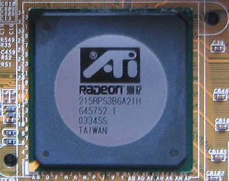
Чипсет ATI RADEON 9100 IGP является интегрированным решением и содержит в себе графическое ядро ATi Radeon 9200.
Набор логики ATI RADEON 9100 IGP, как и у его интегрированных собратьев и конкурентов, построен по принципу SMA (Shared Memory Architecture - совместное использование памяти). Главный минус SMA – в том, что оперативная память не может обеспечить достаточную полосу пропускания для встроенного графического адаптера. То есть для того чтобы интегрированное графическое ядро не уступало своему внешнему аналогу, необходимо, чтобы пропускная способность памяти была примерно такой же, как у внешней видеокарты на чипсете ATI Radeon 9200. Что же, давайте сравним: у Radeon 9200 пропускная способность памяти составляет 6,4 Гбайт/сек, в зависимости от использованного типа памяти и установленных настроек конфигурирования подсистемы памяти. У интегрированного ядра такая пропускная способность невозможна – на канале с той же шириной работает еще и процессор. Из всего вышесказанного можно сделать ещё один вывод – производительность графического ядра будет “прыгать” в зависимости от того, чем в данный момент занят процессор.
Технические характеристики встроенного ядра таковы:
• 256-битный GPU с частотой 300 МГц
• Память: 128 Мбайт макс. (8/16/32/64 или 128 Мбайт)
• DirectX 8.1
• Пиксельные конвейеры: 2x1 (один блок на конвейер)
• Аппаратная поддержка T&L
• SuperSampling FSAA
• Анизотропная фильтрация
• Hyper-Z
• ТВ-выход
• RAMDAC 400 МГц
Давайте немного подробнее остановимся на интегрированной графике ATI RADEON 9100 IGP. Память RAMDAC 400 МГц справляется со своей задачей более чем хорошо, обеспечивая разрешения вплоть до 2048x1536x32 бит при 85 Гц. Что касается 3D-графики, то здесь у ATI также всё в порядке. Судите сами: ATI RADEON 9100 IGP является единственным решением с поддержкой DirectX 8.1 среди интегрированных наборов логики для платформы Socket 478; решения конкурентов так и остались на уровне DirectX 7. Поддержка пиксельных шейдеров версии 1.4 тоже будет очень кстати.
Встроенное графическое ядро имеет расширенные функции проигрывания DVD (аппаратный iDCT и компенсация движения), DV- выход и TV-out (последние реализованы именно в интегрированном ядре и не требуют дополнительных контроллеров).
Также стоит отметить ещё одну интересную особенность данного набора логики: будущие версии этого чипсета получат возможность подключения трёх мониторов (технология Surroundview), два из которых будут подключаться к установленной внешней видеокарте, поддерживающей ATi Dual-Head, а третий к выходу на материнской плате.
Чипсет выполнен по классической двухчиповой схеме: северный мост RS300 и южный мост IXP250 соединены шиной A-Link, пропускная способность которой - 266 Мбайт/сек. Немного по современным меркам. Увы, но южный мост IXP250 также не может похвастаться технологической насыщенностью и выглядит на сегодняшний день немного примитивно. Судите сами: два канала ATA-100, 6 портов USB 2.0 портов, шестиканальный звук, сетевые возможности реализованы контроллером 3СOM 10/100 Ethernet. Главный минус – это, конечно, отсутствие поддержки Serial-ATA. Похоже на то, что решение компании ATI отказаться от SATA - это не прихоть, просто ATI столкнулась с проблемами при реализации последнего.
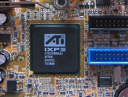
Помимо IXP250, вкупе с набором логики ATI RADEON 9100 IGP могут поставляться ещё два южных моста IXP200 и IXP150, которые являются упрощенными версиями IXP250 - в обоих отсутствуют функции энергосбережения, а в IXP150 отсутствует еще и сетевой контроллер.
Для возможности сравнения ATI Radeon 9100 IGP с конкурентами приведём таблицу, в которой собраны технические характеристики детища ATI и ещё двух актуальных на сегодняшний день чипсетов производства Intel и SIS.
Читайте также: