Matek f405 std подключение crossfire
![]()
IntoFPV Forum › Hardware Discussion › Flight Controller

Matek F405 & Crossfire with Telem
coyote_dc5
Member
I've fitted crossfire two three quads in the past (1 emax AIO & 2 iFlight F4s) and I just wired up to a spare UART RX/TX and away I went. Telemetry just worked right away. I've now got a Matek F405-OSD and i'm reading up about needing to do soft serial resource mappings to get telemetry working.
The links do seem to just reference FrSky so I'm just wondering if I need to concern myself here.
The Matek docs say there are 5 UARTS and UART 2 is hard inverted already so I just need help deciding whether to go into UART 2 or just another random spare one
iFlight Green Hornet 1 | Emax Tinyhawk Freestyle 2 | Emax Tinyhawk 2
ISDT 608 & Balance Board | Eachine EV800D | Taranis Qx7 | TBS Crossfire Mini v2
SnowLeopardFPV
Member


Posts: 17,249
Threads: 439
Likes Received: 6,664 in 4,991 posts
Likes Given: 1,367
Joined: Jun 2018
Reputation: 637
You just need to wire up your Crossfire Nano RX to a normal UART and it will just work. I have a Matek F405-STD with a Crossfire Nano wired up and working fine on one of the standard UARTs. All that SoftSerial remapping stuff is for FrSky receivers only. I had to do all that before I switched to using Crossfire.
![]()
IntoFPV Forum › General Discussion › Beginner Questions
Crossfire nano rx and Matek F405 Wing FC
jimv
Member
I had a AR-900mm wing with Matek F405-wing FC GPS w/compass, TBS Nano Rx receiver and TBS unified hv VTX everything work well then I had a flyaway and lost everything.
I’m replacing it with same thing and all the same parts but now I can’t get the gps Sats and coordinates telemetry to show up now on my Taranis X9D +2019 radio and I replace the new FC, GPS and nano rx receiver with new again but still will not work. I think the nano rx is what sends telemetry back to radio but did they make two nano rx one that sent the Sats and coordinates and one that didn’t?
Or is it the GPS w/compass that is sending it? I’m lost and don’t understand the only thing I’m doing different is I soldered the pins in instead of soldering straight to the FC board and using iNAV 3.0.1 instead of iNAV 2.6.1 anyone have any idea what I could be doing wrong?
Jim
kafie1980
Just trying to be helpful
Posts: 3,324
Threads: 30
Likes Received: 901 in 761 posts
Likes Given: 291
Joined: Aug 2020
Reputation: 78
You have replaced too many things for me to nail down what is the actual cause. I would look over the soldering job again and use a multimeter for continuity tests.
Does everything power up? I mean the GPS etc?
First, every crossfire nano rx sends telemetry.
Ensure you have telemetry on in Betalight Configurator> Configuration tab:
![[Image: configure-smart-port-in-betaflight-confi. 24x729.jpg]](https://oscarliang.com/ctt/uploads/2015/12/configure-smart-port-in-betaflight-configuration-tab-1024x729.jpg)
Also ensure you have telemetry on for the crossfire nano rx via the TBS Agent X app or the Crossfire Lua script:
![[Image: JUMPER-T16-CROSSFIRE-LUA-SCRIPT-SETUP-RX-RECEIVER.jpg]](https://oscarliang.com/ctt/uploads/2019/12/JUMPER-T16-CROSSFIRE-LUA-SCRIPT-SETUP-RX-RECEIVER.jpg)
Can you confirm that you are getting a GPS lock in Betaflight?
Ensure you have the Betaflight Configurator> Ports tab setup for GPS as the Sensor Input for the correct UAR:
![[Image: portstabgps.jpg]](https://www.currykitten.co.uk/storage/2020/06/portstabgps.jpg)
Also turn on GPS from the Betaflight Configurator> Configuration tab:
![[Image: configtabgps.jpg]](https://www.currykitten.co.uk/storage/2020/06/configtabgps.jpg)
There should be a GPS icon in the top right corner and also you can check it via the GPS tab:


Due to flash memory limitations, this board does not include all ArduPilot features. See Firmware Limitations for details.
RC Input
TThe SBUS pin, is passed by an inverter to R2 (UART2 RX), which by default is mapped to a timer input instead of the UART, and can be used for all ArduPilot supported receiver protocols, except CRSF which requires a true UART connection. However, bi-directional protocols which include telemetry, such as SRXL2 and FPort, when connected in this manner, will only provide RC without telemetry.
To allow CRSF and embedded telemetry available in Fport, CRSF, and SRXL2 receivers, the R2 pin can also be configured to be used as true UART2 RX pin for use with bi-directional systems by setting the BRD_ALT_CONFIG to “1” so it becomes the SERIAL7 port’s RX input pin.
With this option, SERIAL7_PROTOCOL must be set to “23”, and:
- PPM is not supported.
- DSM/SRXL connects to the R2 pin, but SBUS would still be connected to SBUS.
- FPort requires connection to T2 and R2 via a bi-directional inverter. See FPort Receivers .
- CRSF also requires a T2 connection, in addition to R2, and automatically provides telemetry.
- SRXL2 requires a connection to T2 and automatically provides telemetry. Set SERIAL6_OPTIONS to “4”.
Any UART can be used for RC system connections in ArduPilot also, and is compatible with all protocols except PPM (SBUS requires external inversion on other UARTs). See Radio Control Systems for details..
Connecting a GPS/Compass module
This board does not include a GPS or compass so an external GPS/compass should be connected as shown below in order for autonomous modes to function.

A battery must be plugged in for power to be provided to the 5V pins supplying the GPS/compass modules. USB power is not provided to peripherals.
Variants
In addition to STD and CTR versions, there are older variants called -AIO and -OSD that have been declared end-of-life by Mateksys. Both use the ICM20602 IMU, like the STD version. Neither have an onboard barometer. While the -AIO has I2C pads exposed, the -OSD version does not.
For the -STD version please use the MatekF405-STD type firmware. For the -CTR version with MPU6000 please use the MatekF405 type firmware. For the MatekF405-Wing which has an essentially different board layout please use the dedicated firmware. Please note that ArduPilot does not support -AIO and -OSD versions per default as additional hardware and / or software adjustments are required.
The MatekF405-CTR has a firmware version supporting bi-directional Dshot labeled “MatekF405-bdshot”. Note this is only supported for outputs 1-4 in this version.
Dshot capability
Specifications
- Processor
- STM32F405RGT6 ARM (168MHz)
- ICM20602 IMU on STD version, MPU6000 on CTR version
- BMP280 barometer (STD and CTR)
- 184A Voltage & current sensor on CTR version
- 5x UARTS
- 6x PWM outputs (7 on -STD)
- 1x RC input PWM/PPM, SBUS
- I2C port for external compass and airspeed sensor (STD, CTR and AIO)
- USB port
- Built-in OSD
- MicroSD slot
- 36x36mm PCB with 30.5mm mounting holes
- STD: 7g
- CTR: 10g
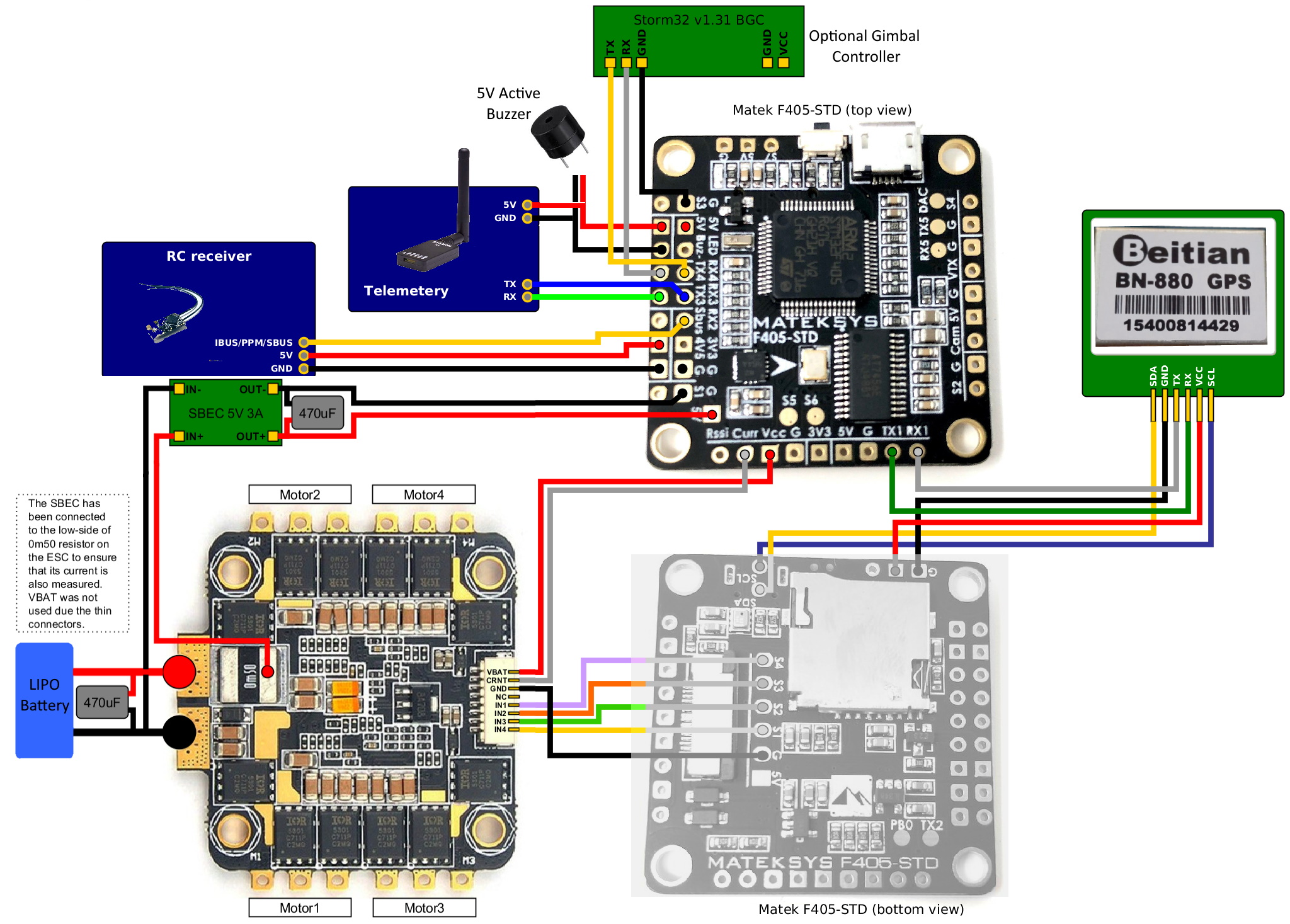
Wiring Diagram
![../_images/MatekF405-STD.jpg]()
Questions, issues, and suggestions about this page can be raised on the forums. Issues and suggestions may be posted on the forums or the Github Issue Tracker.
![Перчатка управления минидроном!]()
![EMAX - Tiny Hawk - Обзор]()
![Мощный но дешевый Kit гоночного квадрокоптера]()
![Eachine EV800 - Обзор видеошлема]()
![Обзор DJI Mavic Pro + Тест на дальность - YouTube]()
![Настройка квадрика с помощью смартфона.]()
![Eachine EV800 Видео Шлем для FPV Полётов по Камере]()
![Mavic 2 Pro распаковка и сравнение с Mavic Pro]()
![Обзор дрона EO12W]()
![Razor X125 - Micro FPV Racing Drone Test Flight Review]()
![Дешевые и практичные видеоочки Eachine EV100]()
![Обзор Mavic Air. Падение Mavic Air. Порез винтами.]()
Вам подойдут любые моторы! Смотрите раздел статей про сборки дронов - там есть наборы. Не имея понимания задачи я остерегусь чего то советовать
Скажу честно - поставьте готовый полетный контроллер, головняка меньше будет. Сейчас полетники самонастраивающиеся, а вам, кроме программирования и связки ардуринки, придется очень долго подбирать.
Здравствуйте, имеется полетник matek 722se и express elrs ES900RX, спаял всё правильно, начал прошивать передатчик, а он ошибку выдаёт, я начал читать, нашел что светодиод должен мигать когда не.
![INAV-]()
![Matek F405-CTR Лучший полетник под INAV!]()
![INAV от А до Я. Настройка квадрокоптера с нуля.]()
![Гусеницы на WPL. Тесты. Выводы!]()
![Ставим ардукоптер на бомж-дальнолет]()
![Обзор и настройка Betaflight OSD на примере контроллера Matek F405-OSD.]()
![Обзор и мануал по HUBOSD, Matek and Realacc.]()
![Быстрое сравнение Hubosd плат от Matek и Realacc]()
![Matek F405-OSD Обзор и подключение.]()
![FrSky XSRF4O Обзор,настройка и тесты.]()
Вам подойдут любые моторы! Смотрите раздел статей про сборки дронов - там есть наборы. Не имея понимания задачи я остерегусь чего то советовать
Скажу честно - поставьте готовый полетный контроллер, головняка меньше будет. Сейчас полетники самонастраивающиеся, а вам, кроме программирования и связки ардуринки, придется очень долго подбирать.
Здравствуйте, имеется полетник matek 722se и express elrs ES900RX, спаял всё правильно, начал прошивать передатчик, а он ошибку выдаёт, я начал читать, нашел что светодиод должен мигать когда не.
Where to Buy
Default UART order
- SERIAL0 = console = USB
- SERIAL1 = Telemetry1 = USART3
- SERIAL2 = Telemetry2 = UART4
- SERIAL3 = GPS1 = USART1
- SERIAL4 = GPS2 = UART5
- SERIAL5 = User = USART2 (TX only unless BRD_ALT_CONFIG = 1, then RX is available)
Serial protocols can be adjusted to personal preferences.
Читайте также: