
Lte pci что это
Если Вам приходилось пользоваться интернетом через смартфон или 4G модем с вайфай роутером, то так или иначе Вы замечали, что скорость не всегда постоянная ,а одним из условий максимальной отдачи ваших устройств является достаточный уровень сигнала LTE .
Оценить качество связи с базовой станции сотового оператора можно по параметрам отображаемым в техническом меню смартфона или на страничке настройки модема.
Для наиболее популярных модемов Huawei 3372-320 страничка настройки доступна по адресу: 192.168.8.1
После входа в настройки выбираем пункт Дополнительно , затем подпункт Система и прокручиваем вниз
Нам доступно четыре параметра так или иначе характеризующие уровень сигнала:
RSRQ аббревиатура от английского reference signal received quality - среднее значение качества принятого сигнала, характеризует соотношение полезного сигнала к уровню шума
RSRP от англ. reference signal received power среднее значение мощности принятого сигнала, характеризует энергетическую составляющую сигнала
RSSI от англ recieved signal strength indicator индикатор силы принимаемого сигнала, статистический параметр условно отображающий уровень приема
SINR от англ. signal interference noise ratio отношение сигнал-шум, показывает насколько полезный сигнал сильнее шумов.
В интернете можно найти очень много статей относительно того, какими должны быть значения этих параметров, большинство авторов , по моему мнению не имеют практического опыта и просто перепечатывают одно и тоже. Например, очень часто вижу такое утверждение: "параметр SINR должен быть 20 и больше, иначе высокой скорости вам не видать, у Вас плохая связь и т.д." на практике же , при значении этого параметра выше 0 уже практически нет положительного влияния на скорость соединения, а значение 20 и выше можно увидеть только в прямой видимости от вышки на расстоянии до 1 км. На скриншоте выше параметры сигнала на моем роутере, как видно синр у меня слабенький, но скорость при этом нормальная:
Я пробовал использовать наружные антенны, уровень сигнала в этом случае значительно выше, но на скорость это не влияет - это потолок базовой станции с которой идет прием.
Поэтому далее я приведу МИНИМАЛЬНЫЕ значения уровня LTE 4G, начиная с которых можно считать , что у Вас нормальный сигнал, значения эти получены на практике при монтаже систем усиления сотовой связи на территории Томской области нашей компанией (по ссылке доступен наш сайт):
RSRP . -95 и ниже, шкалы сигнала в сотовой связи отрицательные, поэтому уровень -85 это более сильный сигнал чем -95
RSSI . -70 и ниже
RSRQ я обычно вообще не мониторю, поскольку информативность этого параметра очень низкая.
Рекомендованные характеристики канала должны выглядеть примерно так:
RSSI -55. -65 , RSRP -75. -90, SINR 8 и более
Стоит учитывать , что если Вы планируете устанавливать усилитель сотовой связи (аля репитер в простонародье) эти параметры нужно уменьшить на значение шума вносимого ретранслятором, как правило это значение около 6дБ.
Почему же так происходит, что с определенного уровня сигнала дальнейшее улучшение-усиление бессмысленно?
В цифровом сигнале присутствует избыточность, те цифровой поток от вашего модема к базовой станции несет не только полезную информацию, но и проверочные символы, которые используются для того, чтобы исправлять ошибки в полезной информации на приемной стороне, которые появляются в процессе воздействия на сигнал различных помех, шумов, переотражений и т.д. Пока этой избыточности хватает - ваша скорость максимальная, как только ошибок становится настолько много, что заложенная избыточность не справляется, начинают отправляться повторные запросы на отправку поврежденных пакетов данных,а это приводит к значительному снижению скорости.
Поэтому если уровни сигнала на Вашем модеме не хуже приведенных в статье, а скорость ниже, стоит смотреть в сторону другого оператора сотовой связи или более современного модема 6 категории, но о этом в другой статье
В магазинах приложений для смартфонов можно найти много программ для оценки качества сигнала сотовой сети и определения местоположения сотовых вышек. Они используются для настройки модемов и усилителей сигнала, а также поиска причин низких скоростей. По просьбе читателя сегодня я сделаю обзор индикаторов сети LTE из приложения "Сотовые вышки". Хотя и в других программах вы сможете встретить те же данные.
PCI
Ну и самое сложное на закуску: PCI он же Physical Cell Identifier , то есть физический идентификатор соты. Он используется смартфоном для переключения между сотами, например, в случае ухудшения качества от обслуживающей соты или когда нагрузка на станции становится слишком большой сеть может скомандовать перейти на другую станцию.
Главное отличие от предыдущего идентификатора в том, что PCI используется смартфонами, а CI - сотрудниками оператора. Отсюда можно сделать вывод, что PCI не может быть одинаковым в одном месте сразу у нескольких сот. Иначе смартфон просто не сможет понять отличие между ними. Такая ситуация может обернутся большими проблемами, вплоть до существенного падения скоростей передачи данных, недоступности сети и т.п.
Поэтому диапазон PCI значительно больше: от 0 до 503. Причём PCI состоит из 2-х отдельных идентификаторов PSS и SSS. PSS может быть равен 1,2 или 3, а SSS от 0 до 167. PCI вычисляется по формуле PCI = 3*SSS + PSS. PSS не может быть равен у двух сот с пересекающимся покрытием. Именно для этого и было введено такое разделение.
LTE PCI Formula Calculation
PCI mod30
Just like in downlink, every 3rd or 6th PCI collides on the reference signals, every 30th PCI has the same pattern of uplink reference signals. In uplink, the reference signals are present in the central symbol of the slot and their pattern or base sequence repeats for every 30th PCI. In case, two adjacent cells have same PCI mod30, then the cell can have difficulty in decoding which can result in higher block error rate in uplink. However, this is not a critical issue and very rarely observed in the commercial networks.
RSSP vs RSRQ vs RSSI vs SINR
Below is a chart that shows what values are considered good and bad for the LTE signal strength values:

PSS and SSS in LTE
So, if SSS is equal to 5 and PSS is equal to 1 then the PCI would be 16. A basic rule of thumb is that the neighboring cells should not have the same “PSS” value. Usually, a site with 3 cells use same SSS value but different PSS value such that the PCIs for cell 1,2 and 3 will be 0,1 and 2.
Within the cell, the channels are scrambled using the PCI which means that the PCI serves as the seed for the cell’s permutation algorithm. That’s why, the UE has to decode the PSS and SSS before reading any other channel as it needs to get the PCI which tells about the permutation used in the cell.
CI ( Cell ID )
Cell ID - это идентификатор соты. В отличие от предшествующих стандартов 2G и 3G, в сети 4G он идентифицирует соту лишь в пределах одной базовой станции (eNodeB). К примеру, на станции есть три сектора, направленные, в разные стороны. Тогда им можно присвоить идентификаторы 1, 2 и 3 соответственно. У соседней станции будут использованы те же самые цифры для обозначении соты 1-3.
Единственное ограничение, что номера Cell ID не должны повторятся внутри одной станции LTE. Поэтому для обозначения разных частотных диапазонов (BAND) используют разные CI. Например, 1-3 для 1800 МГц, 4-6 для 2600 МГц, 7-9 для 800 МГц и т.п.
PCI Planning allocation Rules
Вместо завершения
Эту статью я написал по просьбе читателя. Написана она максимально простым и понятным языком, чтобы не вдаваться в подробности и не грузить вас сложными основами. Если вас интересует суть происходящего - есть множество технической литературы с сухим изложением, англоязычными терминами и математическо-физическими выкладками. Буду рад новым идеям для статей - пишите в комментариях.

PCI planning is one of the most important things to understand while planning an LTE network and it is usually left untouched in most of the LTE manuals and text-books. As already explained, the PCI is decoded using the SSS and the PSS and can be given by the following equation
PCI collisions
In LTE, the PCFICH is one of the channels that gets its location determined based on the PCI. This also means that every PCFICH will repeat its position for some PCIs. Basic rule is that every 50th PCI will have same location of PCFICH for 20MHz channel while every 25th PCI will have same location of PCFICH for 10MHz channels. Such a scenario can cause decoding failures or higher block error rate on PCFICH and since PCFICH is required to decode PDCCH so it can cause DTX (decoding failure of grants on PDCCH).
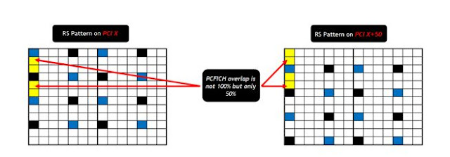
But once again it is difficult to observe in FDD systems and another fact that most of the documents overlook is that PCFICH consists of 4REGs. Each REG has 4 REs but we have reference signals in a LTE system after every 2 REs. So, each PCFICH REG will have Reference Signals embedded inside and that means that 2 PCFICHs usually do not overlap each other completely.
Understanding dBm vs dB
dB is ratio between two power values while dBm is used to express an absolute value of power. So when we mention RSRP and RSSI we shall always use dBm since we are talking about absolute power values but we need to use dB with RSRQ since it is the ratio of RSRP to RSSI
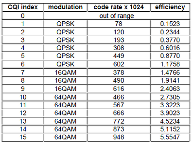
The Channel Quality Indicator (CQI) contains information sent from a UE to the eNode-B to indicate a suitable downlink transmission data rate, i.e., a Modulation and Coding Scheme (MCS) value. CQI is a 4-bit integer and is based on the observed signal-to-interference-plus-noise ratio (SINR) at the UE. The CQI estimation process takes into account the UE capability such as the number of antennas and the type of receiver used for detection. This is important since for the same SINR value the MCS level that can be supported by a UE depends on these various UE capabilities, which needs to be taken into account in order for the eNode-B to select an optimum MCS level for the transmission. The CQI reported values are used by the eNode-B for downlink scheduling and link adaptation, which are important features of LTE.
In LTE, there are 15 different CQI values randing from 1 to 15 and mapping between CQI and modulcation scheme, transport block size is defined as follows (36.213)

Cell ID sets the physical (PHY) layer Cell ID. This PHY-layer Cell ID determines the Cell ID Group and Cell ID Sector. There are 168 possible Cell ID groups and 3 possible Cell ID sectors; therefore, there are 3 * 168 = 504 possible PHY-layer cell IDs. When Cell ID is set to Auto, the demodulator will automatically detect the Cell ID. When Cell ID is set to Manual, the PHY-layer Cell ID must be specified for successful demodulation.
The physical layer cell id can be calculated from the following formula:
When Sync Type is set to C-RS, the Cell ID Auto selection will be disabled, and Cell ID must be specified manually. This is because the demodulator needs to know the values of the C-RS sequence to use for synchronization and because Cell ID determines these values. See RS-PRS for more information.
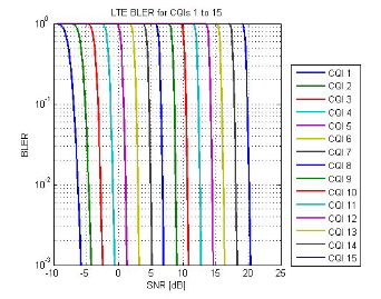
3GPP TS 34.121, F.6.1.1 defines block error ratio (BLER) as follows: "A Block Error Ratio is defined as the ratio of the number of erroneous blocks received to the total number of blocks sent. An erroneous block is defined as a Transport Block, the cyclic redundancy check (CRC) of which is wrong."
- PDCCH channel can take 1 to 3 symbols out of 14 in a subframe. Assuming that on average it is 2.5 symbols, the amount of overhead due to PDCCH becomes 2.5/14 = 17.86 %.
- Downlink RS signal uses 4 symbols in every third subcarrier resulting in 16/336 = 4.76% overhead for 2×2 MIMO configuration
- The other channels (PSS, SSS, PBCH, PCFICH, PHICH) added together amount to ~2.6% of overhead
- Pilot overhead (4 Tx antennas) = 14.29%
- Common channel overhead (adequate to serve 1 UE/subframe) = 10%
- CP overhead = 6.66%
- Guard band overhead = 10%
- Pilot overhead = 14.3%
- Random access overhead = 0.625%
- CP overhead = 6.66%
- Guard band overhead = 10%
- Channel bandwidth
- Network loading: number of subscribers in a cell which impacts the overhead
- The configuration & capability of the system: whether it’s 2×2 MIMO, SISO, and the MCS scheme.

Другое
Также в программах вроде Сотовые вышки представлено множество других данных. Большая часть из них - это идентификаторы оператора (MCC MNC), станции (eNodeB ID) и конкретной соты (CID PCI). Большого интереса для настройки модема или усилителя они не представляют. Но если вам интересно - пишите в комментариях. Обязательно расскажу
Продолжаю рассказывать об идентификаторах и разных сокращения в сетях LTE. Сегодня речь пойдёт о CI, PCI и EARFCN. Не случайно я их объединил в одну группу, так как все они относятся к обозначениям конкретной соты и частотного диапазона у оператора. Смартфон регулярно использует их, например, в процессе выбора соты после включения, а также поиска новой соты когда мы движемся и качество/уровень сигнала падают.
LTE PCI Range :
LTE PCI Range is 0-503
LTE PSS Range is 0 to 2
LTE SSS Range 0 to 167
Что такое Reference Signal
Чтобы было проще разбираться дальше сначала расскажу немного о структуре сигнала в LTE. Сотовая станция кроме того что передаёт и принимает пользовательские данные на смартфоны также вещает служебные каналы. Они нужны для поиска смартфоном своей сети, считывания системных настроек и получения команд от сотовой станции. Самым важным из служебных каналов является пилотный сигнал. В LTE он называется Reference Signal , т.е. опорный сигнал.
Он нужен для выравнивания структуры сигнала между сотовой станцией и смартфоном, то есть простым языком - синхронизации. Кроме того, по этому сигналу производится оценка качества и уровня сигнала именно в той полосе, которая предназначена для данного смартфона. Дело в том, что вся полоса LTE (5-20 МГц) поделена на узкие полосы - subcarriers (поднесущие) по 180 кГц. И только часть из них предназначена для конкретного смартфона в конкретный момент времени.
Ну а теперь перейдём непосредственно к индикаторам.
Reference Signals recap: OFDMA Channel Estimation
In simple terms the Reference Signal (RS) is mapped to Resource Elements (RE). This mapping follows a specific pattern (see to below).
- So at any point in time the UE will measure all the REs that carry the RS and average the measurements to obtain an RSRP reading.
- Channel estimation in LTE is based on reference signals (like CPICH functionality in WCDMA)
- Reference signals position in time domain is fixed (0 and 4 for Type 1 Frame) whereas in frequency domain it depends on the Cell ID
- In case more than one antenna is used (e.g. MIMO) the Resource elements allocated to reference signals on one antenna are DTX on the other antennas
- Reference signals are modulated to identify the cell to which they belong


Качество сигнала LTE
SINR - Signal to Interference + Noise Ratio - отношение мощности сигнала к сумме мощности интерференции и помех. Он показывает уровень шума во всей полосе LTE. Чем он ниже - тем хуже будут скорости передачи данных. Его ценность в том, что он показывает шум от всех сотовых станций в конкретном месте. В таких местах смартфону или модему сложнее детектировать сигнал от своей станции и ресурсы сети LTE там ограничены. Поэтому если вам удастся найти место где это индикатор выше - тем лучше. Причём не факт, что это будет открытое место. Выше - не значит лучше.
RSRQ (Reference Signal Received Quality) - показывает качество пилотных сигналов (Reference Signal). Так же как и в предыдущем случае, RSRQ оценивает наличие помех непосредственно в полосе, предназначенной для конкретного смартфона от конкретной станции.
RSSNR (Reference Signal to Signal Noise Ratio) - отношение мощности пилотного сигнала к отношению сигнал/шум. Он показывает на сколько мощность сигнала непосредственно предназначенного для вашего смартфона выше сигнала и шума от других сотовых вышек. Чем он выше - тем лучше. Этот индикатор также хорошо подходит для настройки модема/усилителя как и SINR. Принципы использования аналогичные.
SNR vs. RSRP
- Noise figure = 7 dB
- Temperature = 290 K


PCI mod3 mod6
Let’s dig a bit deeper and understand how different vendors do the PCI planning. One approach is to use the same group (same SSS) on one site (3 sector sites) which is the PCI-Modulus3 planning technique. This is much similar to what is depicted in the Figure 9 (above). The PCI is also used to indicate the location of RS along the frequency axis. Consider that the PCI=X will have the RS located at the first sub-carrier then the PCI=X+1 will move the RS downwards by one sub-carrier and PCI=X+2 will move it down by another sub-carrier. The point to note is that there are 2 RS per RB per antenna port in the 1st OFDM symbol. But there are another 2 RS for the second antenna port on the same symbol. These 2 RS are zero-powered (also known as DTX – discontinuous transmission) on the first antenna port. So, when the PCI is changed to X+3, then the RS for antenna port0 moves to the same position as RS for antenna port1 of the PCI=X. This means that for every PCI=X, any other PCI with value of X+3(n) – where “n” is an integer, will have a collision on Reference Signal between the two ports. This is known as the PCI mod3 issue.

However, if the system is only a single port system like most of the IBS systems, then the PCI mod3 will not impact because there will be no reference signals on the second port. Instead, the rule will change to PCI mod6.
An important point to remember is that most of the FDD LTE networks are not time synchronized between sites so the symbols do not usually overlap in time. Therefore, for FDD systems, this rule is not as important as it is for TDD LTE systems which are always time synchronized.
Что такое Reference Signal
Чтобы было проще разбираться дальше сначала расскажу немного о структуре сигнала в LTE. Сотовая станция кроме того что передаёт и принимает пользовательские данные на смартфоны также вещает служебные каналы. Они нужны для поиска смартфоном своей сети, считывания системных настроек и получения команд от сотовой станции. Самым важным из служебных каналов является пилотный сигнал. В LTE он называется Reference Signal , т.е. опорный сигнал.
Он нужен для выравнивания структуры сигнала между сотовой станцией и смартфоном, то есть простым языком - синхронизации. Кроме того, по этому сигналу производится оценка качества и уровня сигнала именно в той полосе, которая предназначена для данного смартфона. Дело в том, что вся полоса LTE (5-20 МГц) поделена на узкие полосы - subcarriers (поднесущие) по 180 кГц. И только часть из них предназначена для конкретного смартфона в конкретный момент времени.
Ну а теперь перейдём непосредственно к индикаторам.
Уровень сигнала LTE
RSSI (Received Signal Strength Indicator) - уровень принимаемого сигнала. Он показывает уровень сигнала, который принимает смартфон во всей полосе (5-20 МГц). Причём сигнал может быть принят с нескольких станций. Этого индикатора нет в программе Сотовые вышки
RSRP (Reference Signal Received Power) - мощность пилотного сигнала, то есть Reference Signal. Очевидно, что мощность в отдельной поднесущей будет ниже, чем во всей полосе. Поэтому значения этого индикатора всегда на 20-30dB ниже RSSI. Но этот показатель ценен тем, что показывает мощность сигнала непосредственно предназначенного для вашего смартфона/модема от конкретной станции. Именно его нужно использовать для настройки модема или усилителя сигнала. Чем он выше - тем лучше.
Impact of serving cell power to RSRQ:
Example for noise limited case (no interference): If all resource elements are active and are transmitted with equal power, then
- RSRQ = N / 12N = -10.8 dB for 1Tx
- RSRQ = N / 20N = -13 dB for 2Tx taking DTX into account
(because RSRP is measured over 1 resource element and RSSI per resource block is measured over 12 resource elements).
Remember that RSSI is only measured at those symbol times during which RS REs are transmitted – We do not have to take into the count DTx.
So, when there is no traffic, and assuming only the reference symbols are transmitted (there are 2 of them within the same symbol of a resource block) from a single Tx antenna then the RSSI is generated by only the 2 reference symbols so the result becomes
- RSRQ = N / 2N = -3 dB for 1Tx
- RSRQ = -6dB for 2Tx
SSS Correlation Issue
There is another known rule that is not really considered as it has no evident impact but I thought it is worth mentioning. As explained, each PCI is made up of PSS and SSS. Each SSS is made up of two length-31 binary m-sequences (m0 and m1) but since SSS are 168 in count so these length-31 sequences are bound to repeat. So, each time m0 or m1 repeat itself, the overall correlation between those 2 SSS values is much higher – in other words such SSS can interfere with each other. As an example, SSS value of 9 can have interference with 10 other SSS values.
However, this type of interference has no effect on LTE KPIs and if the UE fails to decode SSS in first subframe, it can still decode it in the 6th subframe as SSS repeats twice within 10ms. So, such an issue, if observed might delay network entry by 5 to 10 ms which does not have any considerable impact.
If you have any questions or feedback regarding PCI Planning, simply drop a comment below and I will surely get back to you.
PCI same usage
Since we have 504 PCIs so this rule is usually not difficult to follow.
- The same site should not use the same PCI again on the same frequency
- The NBRs of the site should not have the same PCI on the same frequency
- Ideally, two NBRs of the site should not have same PCI between them. For instance, Cell-A has NBR Cell-B and Cell-C and both of them have the same frequency, then the PCI of Cell-B and Cell-C should not be identical. This is difficult to maintain in a LTE network but this issue can cause PCI confusion and handover failures

Some important indicator LTE drive test parameters:
1. RSRP : Reference Signal Received Power.
2. RSRQ : Reference Signal Received Quality.
3. RSSI : Received Signal Strength Indicator.
4. SINR : Signal to Interference Noise Ratio.
5. CQI : Channel Quality Index.
6. PCI : Physical Cell Identity.
7. BLER: Block Error Ratio.
8. DL Throughput : Down Link Throughput.
9. UL Throughput : Up Link Throughput
This is the common key performance parameters for LTE drive test parameter we have to work out for LTE drive test task.
RSRP – The average power received from a single Reference signal, and Its typical range is around -44dbm (good) to -140dbm(bad).

Reference Signal Received Quality (RSRQ) is defined as the ratio N×RSRP/(E-UTRA carrier RSSI),
where N is the number of RB’s of the E-UTRA carrier RSSI measurement bandwidth.
The measurements in the numerator and denominator shall be made over the same set of resource blocks.
RSSI – Represents the entire received power including the wanted power from the serving cell as well as all co-channel power and other sources of noise and it is related to the above parameters through the following formula:
Where N is the number of Resource Blocks of the E-UTRA carrier RSSI measurement bandwidth.
RSSI (Received Signal Strength Indicator) is a parameter which provides information about total received wide-band power (measure in all symbols) including all interference and thermal noise. RSSI is not reported to e-NodeB by UE. It can simply be computed from RSRQ and RSRP that are, instead, reported by UE.
RSSI = wideband power = noise + serving cell power + interference power
So, without noise and interference, we have that 100% DL PRB activity: RSSI=12*N*RSRP
- RSRP is the received power of 1 RE (3GPP definition) average of power levels received across all Reference Signal symbols within the considered measurement frequency bandwidth
- RSSI is measured over the entire bandwidth
- N, number of RBs across the RSSI, is measured and depends on the BW
- Wide band SINR
- SINR for a specific sub-carriers (or for a specific resource elements)

EARFCN
Начну с наиболее общего - EARFCN (E-UTRA Absolute Radio Frequency Channel Number) - это номер канала в сети LTE. Он обозначает центральную частоту, на которой работает данная конкретная сота. Примерами могут служить 1300 - это номер канала Билайн в 1800 МГц или 3200 - номер канала МТС в 2600 МГц в ряде регионов. В зависимости от субъекта РФ эти каналы могут меняться, но в пределах одной области или республики обычно одинаковы у одного оператора.
EARFCN не измеряется в каких-то величинах. Это именно номер канала. Хотя он жёстко связан с частотным диапазоном и конкретным номиналом частоты в МГц. Есть достаточно сложная формула для перевода номера канала в частоту и наоборот. Но лично я, как и большинство моих коллег пользуюсь готовым общедоступным калькулятором .
Throughput Troubleshooting


43 comments:
Lte Drive Test Parameters - Telecom Hub >>>>> Download Now
Lte Drive Test Parameters - Telecom Hub >>>>> Download LINK
Lte Drive Test Parameters - Telecom Hub >>>>> Download Full
THANKS FOR SHARING SUCH A AMAZING WORK
GREAT PIECE OF WORK.
best IT networking company in dubai
thank u for sharing this post Wireless Access Points
THANKS FOR SHARING SUCH A AMAZING WORK
GREAT PIECE OF WORK.
network company in dubai

HOW I GOT MY LOAN FROM THIS GREAT COMPANY
They offer all kind of categories of loan they
Blank ATM card
Do you know that you can withdraw cash from any ATM machine .
We have specially programmed ATM cards that can be used to raise cash in ATMs or push, shops and businesses. We sell these cards to all our customers and interested buyers worldwide, the cards have a daily withdrawal limit of $ 5000 at ATM and up to $ 100,000 spending limit in the stores.
We also offer the following services:
1) Western UNION TRANSFERS
2) BANKSLOGINS
3) BANK TRANSFERS
4) CRYPTOCURRENCY MINING
5) PURCHASE OF GIFT CARDS
6) SUBMISSION OF ACCOUNTS
7) WALMART TRANSFERS
8) BITCOIN INVESTMENTS
9) REMOVAL OF NAME FROM DEBIT RECORD AND CRIMINAL RECORDING
10) BANKHACKING

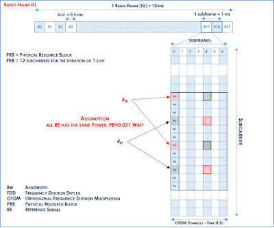
Power Calculation Example
Lets try to calculate RSRP, RSSI and RSRQ for one very simple case of one resource block with 12 sub carriers and 0.5 ms in time domain. Let’s assume the power of reference symbols (shown by red square) and power of other symbols carrying other data channels (shown by blue square) is same i.e. 0.021 watt Since RSRP is linear average of downlink reference signal for given channel bandwidth therefore
While RSSI is total received wide-band power. Therefore we have to add power of all 12 carriers in the given resource block
Читайте также: