
Isis lan adjacency sid advertisement это
Adjacency segment is a strict forwarded single-hop tunnel that carries packets over a specific link between two nodes, irrespective of the link cost. You can configure static adjacency segment identifier (SID) labels for an interface or an interface group.
Configuring a static adjacency SID on an interface causes the existing dynamically allocated adjacency SID to be removed along with the transit route for the same.
For static adjacency SIDs, the labels are picked from either a static reserved label pool or from an ISIS segment routing global block (SRGB).
You can reserve a label range to be used for static allocation of labels using the following configuration:
The static pool can be used by any protocol to allocate a label in this range. You need to ensure that no two protocols use the same static label. ISIS adjacency SIDs can be allocated from this label block through the configuration using keyword label . The label value for the specific adjacency SIDs need to be explicitly configured. The specific label is advertised as the adjacency SIDs for that interface for the specific level and address family. The following is a sample configuration:
SRGB is a global label space that is allocated for the protocol based on configuration. The labels in the entire SRGB is available for ISIS to use and are not allocated to other applications/protocols. Prefix SIDs (and Node SIDs) are indexed from this SRGB.
ISIS Adj-SIDs can be allocated from ISIS SRGB using keyword ‘index’ in the configuration. In such cases, it should be ensured that the Adj-SID index does not conflict with any other prefix SID in the domain. Like Prefix-SIDs, Adj-SIDs will also be configured by mentioning the index with respect to the SRGB. However, the Adj-SID subtlv will still have the SID as a value and the L and V flags are set. The following is a sample configuration:
Static adjacency SIDs can be configured per address family and also based on whether the protection is required or not. Adjacency SIDs should be configured per level per interface at the [ edit protocols isis interface interface-name level level-num ] hierarchy level.
Protected—Ensures adjacency SID is eligible to have a backup path and a B-flag is set in an adjacency SID advertisement.
Unprotected—Ensures no backup path is calculated for a specific adjacency SID and a B-flag is not set in an adjacency SID advertisement.
The following is a sample configuration:
You can use the same adjacent SID for multiple interfaces by grouping a set of interfaces under an interface group and configuring the adjacency SID for that interface group and traffic can be load balanced among the interfaces under the interface group using weight. This can be configured under the [ edit protocols isis interface-group interface_group_name ] hierarchy level.
When segment routing is used in LAN subnetworks, each router in the LAN may advertise the adjacency SID of each of its neighbors. To configure adjacency SID for a LAN interface to a specific neighbor, you should configure the adjacency SIDs under the lan-neighbor configuration at the [ edit protocols isis interface interface_name level level_num lan-neighbor neighbor-sysid ] hierarchy level. The following is a sample configuration:
An adjacency set can be configured by declaring a set of interfaces under an interface group and configuring the adjacency segment for that interface group. The adjacency SID can be picked from the reserved static label pool or ISIS SRGB. Unlike normal interfaces, dynamic adjacency SID is not allocated by default under interface group, in which case the dynamic CLI statement is configured. Interfaces configured under an interface group can also be configured separately as independent interfaces as long as the link-group-protection is not configured. The following is a sample configuration:
Use the following CLI hierarchy for configuring adjacency SID:
Use the following operational CLI commands to verify the configuration:
show isis adjacency detail
The following sample output displays the details of configured and dynamic adjacency SID.
show isis database extensive
The following sample output displays the details of LAN/PTP adjacency SID.
show isis interface-group
The following sample output displays the status information about the specified interface group.
The documentation set for this product strives to use bias-free language. For the purposes of this documentation set, bias-free is defined as language that does not imply discrimination based on age, disability, gender, racial identity, ethnic identity, sexual orientation, socioeconomic status, and intersectionality. Exceptions may be present in the documentation due to language that is hardcoded in the user interfaces of the product software, language used based on RFP documentation, or language that is used by a referenced third-party product. Learn more about how Cisco is using Inclusive Language.
Prerequisites
Configuration Prerequisites
Ensure that segment routing is configured globally.
Ensure that segment routing is configured using IS-IS.
Introduction
This document describes the Intermediate-System to Intermediate-System (IS-IS) protocol adjacency and area types. It shows a sample network scenario and its configuration and some debugs, captures and outputs for better understanding.
Components Used
This document is not restricted to specific software and hardware versions.
The information in this document was created from the devices in a specific lab environment. All of the devices used in this document started with a cleared (default) configuration. If your network is live, make sure that you understand the potential impact of any command.
Book Title
Segment Routing Configuration Guide, Cisco IOS XE Fuji 16.9.x
Book Title
Segment Routing Configuration Guide, Cisco IOS XE Gibraltar 16.12.x
Adjacency SID Forwarding
When the adj-SID value is only configured on a single interface, then the ISIS installs forwarding entries for manually allocated adj-SIDs. The primary path for any Adj-SID is a POP operation over the point-to-point interface for which the Adj-SID is allocated. If the allocated adj-SID is eligible for backup and the backup path is available, IS-IS programs the backup path as well. The backup path for Adj-SID is equal to the backup path computed for the neighbor router-id address.
If the same adj-SID value is configured on multiple links forwarding happens as the following:
Primary path with POP operation is installed via each link where adj-SID is configured with that value.
For each primary path if the adj-SID is configured as protected on the primary interface and backup is available, backup path gets installed. Backup path is represented as a backup path associated with the neighbor router-id address.
Results
Background Information
IS-IS protocol is extensively used as Interior Gateway Protocol (IGP) in Internet Service Provider (ISP) environment. The scope of this document is to provide information regarding IS-IS area types, configuration and troubleshooting. In Cisco world Integrated IS-IS is deployed, meaning IS-IS is routing Internet Protocol (IP) .In this document term IS-IS means ‘Integrated IS-IS’. The real power of IS-IS lies in its use of TLVs (Type-Length-Value) making IS-IS highly extensible protocol. As new features come in, they can be added to protocol using TLVs.
Adjacency SID Advertisement
Manual adj-SIDs are advertised using existing ISIS adj-SID sub-TLV as defined in the ISIS SR extension draft. If the same value of the adj-SID has been provisioned on multiple interfaces, the S-Flag is set in the adj-SID sub-TLV. In the case of manual adj-SID, P flag is always set.
If the provisioned adj-SID has been configured as protected, the B-flag also gets set.
Adjacency-SIDs are always advertised as a label value and never as an index even if the index are used to configure the adj-SID.
Manual Adjacency SID
The existing IS-IS Adj-SID infrastructure that is being used for dynamically allocated Adj-SIDs is extended to support the new persistent Adj-SID requirements. A new CLI command is also introduced to manually assign Adj-SID values for point-to-point links. Multiple Adj-SIDs can be provisioned on a single point-to-point interface. Same Adj-SID can be provisioned on multiple point-to-point interfaces leading to the same or different neighbors.
All manual Adj-SIDs are assigned from a range of labels called Segment Routing Local Block(SRLB). The default SRLB Range is 15000-15999.
Manual Adj-SIDs can be configured as an Index or an Absolute value. If it is configured as an index, the absolute label is calculated as an index + SRLB starting label. For example, if you configure 56 as a manual Adj-SID index, the absolute label would be 15000 + 56 = 15056. If it is configured as an absolute, the label itself is the absolute value. For example, if you configure 56 as an absolute manual Adj-SID, the absolute label would be 56 only. Labels (both index and absolute) can be configured as protected or non-protected. By default, all the labels are non-protected.
Chapter: ISIS Manual Adjacency SID
The Integrated Intermediate System-to-Intermediate System (IS-IS) manual adjacency SID feature provides information about manually provisioned Adjency SIDs.
Manual Adjacency SID
The existing IS-IS Adj-SID infrastructure that is being used for dynamically allocated Adj-SIDs is extended to support the new persistent Adj-SID requirements. A new CLI command is also introduced to manually assign Adj-SID values for point-to-point links. Multiple Adj-SIDs can be provisioned on a single point-to-point interface. Same Adj-SID can be provisioned on multiple point-to-point interfaces leading to the same or different neighbors.
All manual Adj-SIDs are assigned from a range of labels called Segment Routing Local Block(SRLB). The default SRLB Range is 15000-15999.
Manual Adj-SIDs can be configured as an Index or an Absolute value. If it is configured as an index, the absolute label is calculated as an index + SRLB starting label. For example, if you configure 56 as a manual Adj-SID index, the absolute label would be 15000 + 56 = 15056. If it is configured as an absolute, the label itself is the absolute value. For example, if you configure 56 as an absolute manual Adj-SID, the absolute label would be 56 only. Labels (both index and absolute) can be configured as protected or non-protected. By default, all the labels are non-protected.
Configuring Manual Adjacency SID
[index] – (Optional) It is used if the adjacency SID is configured as an index to the SRLB range. If the index keyword is not used the value is expected to represent the absolute value of the label.
[absolute] - (Optional) It is used if the adjacency SID is configured as absolute value.
- It represents the adj-SID label value or index. For the adj-SID to be programmed and advertised, the value/index must fall in the valid SRLB range.
[protected] - (Optional) It is used to protect the manual adj-SIDs. By default, manual adj-SIDs are not protected.
– Level 1 routers form L1 adjacency with L1 and L1/2 Routers
– Level 2 routers form L2 adjacency with L2 and L1/2 Routers
– Level 1/2 routers form L1/2 adjacency with L1/2 Routers
There is no neighbourship between L1 and L2 routers.
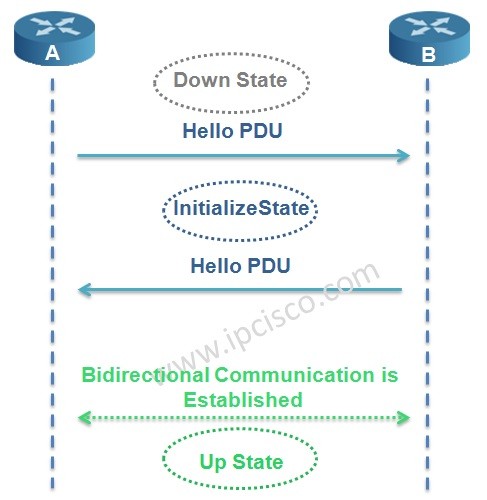
In IS-IS Protocol, adjacency is established with 3-way handshake mechanism. There are three states in IS-IS adjacency. Let’s check the adjacency states of IS-IS Protocol.
In the first place the router adjacency is in Down State. One of the routers, here Router A sends a Hello PDU. When the router B receive this Hello including the MAC address of the sending node Router A, it goes to Initialize State and sends Hello to Router A too. Again, when Router A receives Hello including the MAC address of Router B, bidirectional communication established. And the name of this state is Up State.

IS-IS Protocol Adjacency States As a summary:
– No IS-IS neighbour (Down State)
– RTRA Sends Hello (Initializing State)
– RTRB records MAC address f RTRA and Sends Hello too. RTRA sees MAC address of RTRB. Bidirectional communication established (Up State)
IS-IS Protocol Operation
Beginning with IS-IS adjacency establishment, to the Routing Table establishment, IS-IS Operation has some steps.
We can summarize IS-IS operation in 6 steps. These IS-IS operation steps are given below:
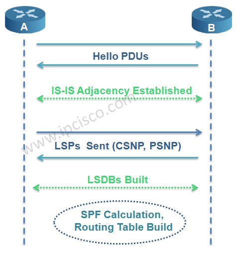
IS-IS Protocol Operation
1. IS-IS Routers are send Hello PDUs to discover the neighbours and establish the adjacency.
2. IS-IS adjacency is established ( mainly authentication, IS-type, MTU must match)
3. LSPs are build by routers about theirselfs and the learned adjacent routers
4. Routers send the LSPs to the adjacent routers.
5. All routers build their LSDB according to these LSPs
6. By SPF algorithm best paths are calculated and routing table is build.
ISIS Manual Adjacency SID
View with Adobe Reader on a variety of devices
Configuring Manual Adjacency SID
[index] – (Optional) It is used if the adjacency SID is configured as an index to the SRLB range. If the index keyword is not used the value is expected to represent the absolute value of the label.
[absolute] - (Optional) It is used if the adjacency SID is configured as absolute value.
- It represents the adj-SID label value or index. For the adj-SID to be programmed and advertised, the value/index must fall in the valid SRLB range.
[protected] - (Optional) It is used to protect the manual adj-SIDs. By default, manual adj-SIDs are not protected.
The documentation set for this product strives to use bias-free language. For the purposes of this documentation set, bias-free is defined as language that does not imply discrimination based on age, disability, gender, racial identity, ethnic identity, sexual orientation, socioeconomic status, and intersectionality. Exceptions may be present in the documentation due to language that is hardcoded in the user interfaces of the product software, language used based on RFP documentation, or language that is used by a referenced third-party product. Learn more about how Cisco is using Inclusive Language.
Information About ISIS Manual Adjacency SID
Segment routing (SR) networks often use SR Traffic Engineering (SR-TE) to influence the path the specific traffic takes over the network. SR-TE tunnels can be provisioned manually on the tunnel head, but often they are calculated and provisioned by the central controller. In many cases operator of the network wants to be able to force the traffic over specific nodes and links.
To force the traffic over a certain node in the SR network operators can use Prefix-SID that is advertised by the node. Many times the anycast Prefix SID is used which forces the traffic to go over specific location where multiple nodes share the same Prefix-SID.
To force the traffic over the specific link, an Adjacency-SID (Adj-SID) is used. The problem with the existing implementation of the Adj-SID is that it is a dynamically allocated value which is in contrast to manually provisioned prefix-SID. The fact that the Adj-SID is dynamically allocated brings a set of problems:
The value is not persistent over reload or process restart.
The value is not known upfront so controller cannot use it unless it has access to the information flooded by IGP (natively or through BGP-LS).
Each link is allocated a unique adj-SID value which prevents the same adj-SID to be shared by multiple links.
To address the above mentioned issues, the adj-SIDs are enhanced and now thay are capable of the following:
Support manually provisioned adj-SID that is persistent over reload and restart.
Support same adj-SID to be provisioned for multiple adjacencies to the same neighbor.
Support same adj-SID to be provisioned for multiple adjacencies going to different neighbors.
Multiple manual Adj-SIDs can be configured for a single adjacency.
Adjacency SID Forwarding
When the adj-SID value is only configured on a single interface, then the ISIS installs forwarding entries for manually allocated adj-SIDs. The primary path for any Adj-SID is a POP operation over the point-to-point interface for which the Adj-SID is allocated. If the allocated adj-SID is eligible for backup and the backup path is available, IS-IS programs the backup path as well. The backup path for Adj-SID is equal to the backup path computed for the neighbor router-id address.
If the same adj-SID value is configured on multiple links forwarding happens as the following:
Primary path with POP operation is installed via each link where adj-SID is configured with that value.
For each primary path if the adj-SID is configured as protected on the primary interface and backup is available, backup path gets installed. Backup path is represented as a backup path associated with the neighbor router-id address.
Requirements
There are no such requirements, however basic understanding of IS-IS and working knowledge of OSPF(Open Shortest Path First) protocol would certainly help.
Chapter: ISIS Manual Adjacency SID
The Integrated Intermediate System-to-Intermediate System (IS-IS) manual adjacency SID feature provides information about manually provisioned Adjency SIDs.
ISIS Manual Adjacency SID
View with Adobe Reader on a variety of devices
Adjacency SID Advertisement
Manual adj-SIDs are advertised using existing ISIS adj-SID sub-TLV as defined in the ISIS SR extension draft. If the same value of the adj-SID has been provisioned on multiple interfaces, the S-Flag is set in the adj-SID sub-TLV. In the case of manual adj-SID, P flag is always set.
If the provisioned adj-SID has been configured as protected, the B-flag also gets set.
Adjacency-SIDs are always advertised as a label value and never as an index even if the index are used to configure the adj-SID.
Network Diagram
The network diagram described below will be used.The addressing scheme is as follows.
Subnets are of type 192.168.X.0 where X is shown between interfaces in the diagram. The loopbacks are of type 192.168.YY.YY, where Y is 1 when Router is R1. So for R1 loopback ip will be 192.168.11.11.
L1, L1/L2 and L2 are Level 1, Level 1-2 and Level 2 routers respectively.

Results
Information About ISIS Manual Adjacency SID
Segment routing (SR) networks often use SR Traffic Engineering (SR-TE) to influence the path the specific traffic takes over the network. SR-TE tunnels can be provisioned manually on the tunnel head, but often they are calculated and provisioned by the central controller. In many cases operator of the network wants to be able to force the traffic over specific nodes and links.
To force the traffic over a certain node in the SR network operators can use Prefix-SID that is advertised by the node. Many times the anycast Prefix SID is used which forces the traffic to go over specific location where multiple nodes share the same Prefix-SID.
To force the traffic over the specific link, an Adjacency-SID (Adj-SID) is used. The problem with the existing implementation of the Adj-SID is that it is a dynamically allocated value which is in contrast to manually provisioned prefix-SID. The fact that the Adj-SID is dynamically allocated brings a set of problems:
The value is not persistent over reload or process restart.
The value is not known upfront so controller cannot use it unless it has access to the information flooded by IGP (natively or through BGP-LS).
Each link is allocated a unique adj-SID value which prevents the same adj-SID to be shared by multiple links.
To address the above mentioned issues, the adj-SIDs are enhanced and now thay are capable of the following:
Support manually provisioned adj-SID that is persistent over reload and restart.
Support same adj-SID to be provisioned for multiple adjacencies to the same neighbor.
Support same adj-SID to be provisioned for multiple adjacencies going to different neighbors.
Multiple manual Adj-SIDs can be configured for a single adjacency.
Configuration Prerequisites
Ensure that segment routing is configured globally.
Ensure that segment routing is configured using IS-IS.
DIS (Designated IS)
In ISIS network, LSDB databases must be synronized. To do this, full mesh or another solution is required. So, in IS-IS Protocol, one router is selected as DIS (Designated IS) and DIS is used to reduce the adjacency in areas. It is like DR in OSPF.
Router with the highest priority and then the highest MAC address is elected as DIS. The default DIS priority is 64. There is no BDR like OSPF. And like OSPF, if you want to prevent the router to be DIS, you can set the priority 0. If a new router added to the ISIS network, the election occurs again. This is not like this in OSPF.
DIS creates a Pseudo Node that is a virtual router. All connected devices in that LAN establish neighbourship with this Pseudo Node.
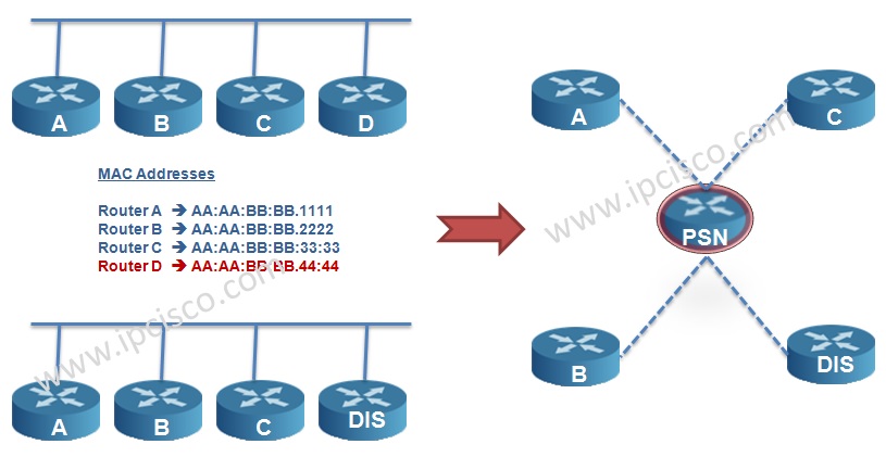
IS-IS Protocol DIS Election DIS is used on multipoint-to-multipoint topologies. It is not used in point-to-point topologies.
Seperate DISs are selected for Level 1 and Level 2.
Configure
IS-IS Areas
In OSPF protocol any of the router’s interfaces can be assigned to a particular area, however the concept of area in IS-IS is different. Here in general, every single router belongs to an Area. The idea of this comes from the fact that IS-IS was initially created to route Connectionless Network Protocol (CLNP) where the address belongs to a device (Router), whereas in Internet Protocol (IP) the address belongs to the particular interface.
IS-IS protocol has two levels or hierarchy, Level 1 and Level 2. Level 1 corresponds OSPF intra-area routing whereas Level 2 corresponds with the OSPF backbone Area 0 routing. Level 2 areas join all the areas with the backbone area. Every Cisco router comes by default as Level 1-2 (L1/L2) router to allow for easy configuration and deployment.
A Level 1 router can become adjacent with the Level 1 and Level 1-2 (L1/L2) router. A Level 2 router can become adjacent with Level 2 or Level 1-2 (L1/L2) router. There is no adjacency between L1 only and L2 only router.
IS-IS Level 1 (L1) Router
An IS-IS Level 1 router has the link state information of its own area for all the intra-area topology. In order to route packets to other areas it uses the closest Level 2 capable (L1/L2) router. Level 1 Area behaves pretty much as OSPF totally stubby area. L1 only router send L1 Hellos.
IS-IS Level 1-2 (L1/L2) Router
An IS-IS L1/L2 router maintains two link state database information. One is for Level 1 and the other for Level 2.Hence two distinct Shortest Path First (SPF) calculations are run, one on Level 1 link state database and other on the Level 2 link state database. IS-IS Level 1-2 router behaves very close to OSPF Area Border Router (ABR). L1/L2 router sends both L1 and L2 hellos.
As default behaviour L1/L2 router will only allow one way passage of prefixes from L1 Area to L2 Area, but not in reverse.
However if it is required to move prefixes from L2 Area to L1 Area then redistribute command under IS-IS configuration is required.
IS-IS Level 2 (L2) Router
An IS-IS Level 2 router has the link state information for the intra-area as well as inter-area routing. L2 router sends only L2 hellos. IS-IS Level 2 area can be compared with OSPF backbone area 0.
IS-IS Adjacency Table
Router Type
L1
L1/L2
L2
L1
L1 Adjacency if Area Id Matches, else no Adjacency
L1 Adjacency if Area Id Matches, else no Adjacency
L1/L2
L1 Adjacency if Area Id Matches, else no Adjacency
L1 and L2 Adjacency if Area id Matches , else only L2 Adjacency
L2 Adjacency , Area Id doesn’t matter
L2
L2 Adjacency , Area Id doesn’t matter
L2 Adjacency , Area Id doesn’t matter
MTU
If one IS-IS router receives an ISIS hello packet with higher MTU than it can support (on the interface) it discards the hello hence the adjacency doesn’t come up. In best practice MTU must be same on both the ends.
Circuit-Type
This attribute is configured on interface and defines what type of hellos i.e. L1 or L2 are sent on a particular interface. A L1/L2 router can selectively send L1 only hellos on one interface and L2 only hellos on its other interface. If L1/L2 router is trying to peer with an L1 only router and L1/L2 interface is configured with “isis circuit-type level-2” it will only send L2 hellos out the interface and the adjacency with L1 router will not come up. Hence routers must send compatible type hellos.
Authentication
IS-IS can separately authenticate hellos and Link State Protocol Data Units (LSP).If hellos are authenticated correctly and LSP authentication fails , the adjacency will come up but updates won’t exchange. So authentication if configured for IS-IS hellos or PDUs (Protocol Data Unit) must match on both the ends.
Capability TLV
If an IS-IS Router does not support the Capability TLV from the other IS-IS Router it silently ignores the TLV. However, there might be events due to capability mismatch when one router reaches INIT state whereas the other one discards the packets and doesn’t form adjacency. So as a general recommendation Capability TLV must match for successful adjacency formation. Discussing in depth details for Capability TLV is beyond the scope of this document.
Network Type
There are only two network types in IS-IS. Broadcast and Point-to-Point. Broadcast is default network type. If one end is configured with “isis network point-to-point” and other end is default network type. The hellos will be discarded and adjacency will not come up. Hence network type must match on both the ends.
Hellos
Hello timers need not match for the adjacency to come up.
IS-IS Adjacency States
There are only three adjacency states in IS-IS.
Down: This is the initial state. Its means that no hellos have been received from the neighbor.
Initializing: This state means that the local router has successfully received hellos from the neighboring router, however it’s not sure that the neighboring router has also successfully received local router’s hellos.
Up: Now it’s confirmed that neighboring router is receiving local router’s hellos.
Configurations
The configuration for the devices for the required diagram is provided below. IS-IS protocol requires configuration both at interface level and globally.
The documentation set for this product strives to use bias-free language. For the purposes of this documentation set, bias-free is defined as language that does not imply discrimination based on age, disability, gender, racial identity, ethnic identity, sexual orientation, socioeconomic status, and intersectionality. Exceptions may be present in the documentation due to language that is hardcoded in the user interfaces of the product software, language used based on RFP documentation, or language that is used by a referenced third-party product. Learn more about how Cisco is using Inclusive Language.
Book Title
Segment Routing Configuration Guide, Cisco IOS XE Fuji 16.9.x
Contents
Читайте также: