
Gizmo 3ds max что это
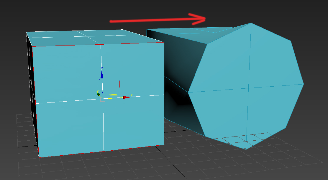
Контейнер, гизмо — Gizmo. Некий фиктивный объект или подобъект, оболочка, в пределах которого действует модификатор или тот или иной эффект.
Материал — Material. Совокупность параметров поверхности, определяющих вид объекта после визуализации. Следует помнить о том, что понятие «материал» относится только к поверхности, но отнюдь не к объему объекта, по той простой причине, что объема в 3ds max нет. Исключением являются только модуль Dynamics и материал типа RayTrace.
Матрица трансформаций — Transformation Matrix. Когда вы создаете объект в 3ds max, создается матрица трансформации, в которую записываются все трансформации (изменения положения, угла поворота и размеров объекта) относительно исходного положения объекта.
Модификатор — Modifier. Процедура, применяемая к объекту или нескольким объектам в целом или выделенным подобъектам. Модификаторы наделяют объекты новыми свойствами.
Нормаль — Normal. В 3ds max каждая поверхность является ориентированной, т. е. имеет лицевую (Front) и обратную (Outer) сторону. В общем случае обратная сторона поверхности не визуализируется, за исключением случаев применения двустороннего материала и принудительной установки визуализации с двух сторон в параметрах визуализатора. Нормаль определяет, какая сторона является лицевой. Термин «Вывернуть нормали» (Flip Normals) означает изменить ориентацию нормалей поверхности. Термин «Согласовать нормали» (Unify Normals) означает ориентировать нормали поверхности в одну сторону, как правило, наружу.
Объект — Object. Объектом в 3ds max является любой элемент в сцене. Объекты могут быть визуализируемыми (например, геометрические примитивы) или невизуализируемыми (источники света, деформаторы, фиктивные объекты и т. д.).
Окно проекции — Viewport. Окно программы, в котором происходит редактирование объектов. Изображение в окне может быть представлено в виде каркаса (Wireframe) или затененном виде (Shaded).
Подобъект — Sub-Object. Это одно из основных понятий 3ds max. Каждый объект состоит из набора подобъектов, например, вершин, граней и т. д. В пределах объекта вы можете редактировать подобъекты независимо друг от друга, но подобъекты всегда принадлежат объекту. Для каждого типа объекта определен свой набор подобъектов. Кроме того, модификаторы также имеют свои подобъекты.
Рендеринг, визуализация — Rendering. Процесс формирования изображения на основе геометрии объектов, параметров материалов, освещения и камеры. Термин «рендеринг» с недавних пор стал общеупотребительным и в русском языке, так как это, все-таки, не просто процесс визуализации. Интересно, что этот термин используется не только в трехмерной графике, но и в пакетах нелинейного монтажа (например, Digital Fusion) и даже в пакетах обработки звука!
Стек модификаторов — Modifier Stack. Список модификаторов, примененных к объекту. 3ds max последовательно, снизу вверх, выполняет модификаторы, примененные к объекту. Вы всегда можете вернуться по стеку модификаторов и изменить параметры текущего модификатора. Любой модификатор в стеке можно переносить, копировать и удалять на любом уровне. Можно также переносить модификаторы из стека одного объекта в стек другого. Будьте внимательны! Некоторые модификаторы (например, Edit Mesh) являются деструктивными, то есть возврат по стеку ниже данного модификатора и изменение параметров объекта на этом уровне может привести к непредсказуемым последствиям. 3ds max, как правило, предупреждает о возможности подобных последствий.
Сцена — Scene. Сценой в 3ds max является совокупность объектов, материалов, анимации и некоторых настроек самой программы — короче, всего того, что записывается в файл проекта.
Моделирование
Полигональное моделирование
В 3ds max следует различать сетчатые объекты (Mesh) и «истинные» полигоны (PolyMesh). Хотя при визуализации все они приводятся к состоянию сетчатого объекта, редактирование их в некоторых случаях отличается.
Вершина — Vertex. Точка в трехмерном пространстве. На основе вершин строится вся остальная геометрия объекта. Вершина является как бы «атомом» любого объекта в 3ds max.
Граница — Border. Группа открытых ребер, т. е. ребер, к которым примыкает только один полигон. Только для полигональных объектов.
Грань — Face. Минимальная поверхность, построенная на базе трех вершин. Если продолжать аналогию, то грань — это «молекула» сетчатого объекта. Для полигонального объекта это понятие не существует в явном виде.
Полигон — Polygon. Для сетчатого объекта — это несколько граней, объединенных «невидимыми» ребрами. Для полигонального объекта это действительно поверхность, ограниченная ребрами.
Ребро — Edge. Линия, соединяющая две вершины. В сетчатом объекте ребра могут быть «видимыми» (Visible) или «невидимыми» (Invisible). В любом случае, ребра существуют. В полигональном объекте нет понятия видимое или невидимое ребро — ребра или есть, или их нет.
Редактируемый полигональный объект — Editable Poly (PolyMesh). Базовое состояние полигонального объекта.
Редактируемый сетчатый объект — Editable Mesh. Базовое состояние сетчатого объекта. В среде специалистов трехмерной графики принято употреблять слово «меш».
Сглаживание/Группа сглаживания — Smooth/Smoothing Group. Каждая модель имеет ограниченное количество граней. Для того чтобы при окончательной визуализации создавалось впечатление, что модель действительно гладкая (например, шар), а не составлена из плоских граней, как это есть на самом деле, предусмотрена операция сглаживания. Визуализатор (Renderer) пытается создать плавные переходы между гранями. Но иногда это не нужно, например, в случае ступенчатого вала. В этом случае в 3ds max предусмотрена возможность объединения граней или полигонов в группы по признаку сглаженности.
Элемент — Element. Несколько граней или полигонов, составляющих единое целое друг с другом и не имеющих общих вершин или ребер с другими элементами. Элементы возникают, например, при присоединении (Attach) одного объекта к другому.
Кривые Безье
Вершина — Vertex. Точка в трехмерном пространстве, на базе которой строится кривая, В отличие от вершины полигонального объекта, вершина кривой может иметь несколько типов: гладкая (Smooth), Безье (Bezier), угол (Corner). Тип вершины влияет на форму кривой.
Редактируемая кривая — Editable Spline. Одно из базовых состояний объекта в 3ds max. Редактирование кривых в 3ds шах очень напоминает редактирование в пакетах векторной графики. Единственное отличие заключается в том, что редактирование происходит в трехмерном пространстве.
Сегмент — Segment. Отрезок кривой, соединяющий две вершины. Сегмент может быть прямолинейным (Line) или криволинейным (Curve).
Сплайн — Spline. Несколько сегментов, последовательно объединенных общими вершинами.
Узел — Handle. Для каждой вершины типа Безье существуют два узла, которые позволяют редактировать форму кривой.
Лоскутное моделирование
Вершина — Vertex. В отличие от вершины кривой, вершины лоскутов имеют три или четыре узла, определяющих форму поверхности. Вершины в поверхности могуч 1 быть внешними, принадлежащими ребрам, и внутренними. И те, и другие определяют форму лоскута.
Лоскут — Patch. Минимальная редактируемая поверхность.
Ребро — Edge. Аналог ребра в полигональной модели с той лишь разницей, что ребро, в данном случае, представляет собой отрезок кривой.
Редактируемая поверхность лоскутов — Editable Patch. Одно из базовых состояний объекта. В двух словах, лоскуты — это поверхности, построенные по тем же принципам, что и кривые Безье.
Материалы
«Суперсглаживание» — Supersampling. Улучшение вида объекта при визуализации за счет применения более скрупулезного алгоритма Полезен например, для улучшения вида при применении очень мелкой текстуры на канале шероховатости (Bump).
Затенитель — Shader. Алгоритм закраски поверхностей в зависимости от параметров источников света.
Координаты наложения текстуры — Mapping Coordinates. Совокупность параметров, необходимых для определения того, как текстура будет наложена на поверхность объекта.
Кривая блика — Highlight graph. Эта кривая определяет, в каких пропорциях происходит смешивание цветов в зависимости от угла падения лучей света на поверхность.
Общий цвет — Ambient Color. Параметр, определяющий цвет граней объекта, не освещенных прямыми источниками света. Насыщенность цвета этих граней зависит только от общего (Ambient) света в сцене. Также этот цвет применяется при использовании глобального освещения.,
Рассеянный цвет — Diffuse Color. Основной параметр, определяющий цвет граней, освещенных прямыми источниками света. Насыщенность цвета таких граней зависит от угла падения лучей на поверхность этих граней.
Сглаживание текстуры — Filtering. Применяется для улучшения вида растровой текстуры при визуализации.
Текстура — Мар. Любое изображение, наложенное на тот или иной параметр. В зависимости от типа параметра, текстура может определять цвет объекта или любой другой параметр, например, шероховатость (Bump). В последнем случае используется только канал яркости текстуры (Level). Текстурой может быть как изображение, взятое из растрового файла, так и процедурная, «автоматическая» текстура, построенная на основе математического алгоритма и рассчитываемая в процессе визуализации.
Цвет блика — Specular Color. Параметр, определяющий цвет граней, освещенных прямыми источниками света под углом, близким к прямому.
Анимация
Ключевой кадр — Keyframe. В ключевых кадрах записываются параметры объектов. Ключевых кадров для анимации должно быть по крайней мере два — в начале и конце анимации.
Контроллер — Controller. Алгоритм, управляющий анимацией того или иного параметра. Существуют контроллеры, основанные на ключевых кадрах и определяющие промежуточное значение параметров в интервалах между ключевыми кадрами, и контроллеры, построенные на математических алгоритмах (например, Noise) или внешних воздействиях (Sound).
Точка привязки — Pivot Point. Точка, принадлежащая объекту, относительно которой происходят все трансформации объекта в процессе анимации. Точка привязки может быть расположена в любом месте, даже вне объекта.
Рендеринг
Глобальное освещение — Global Illumination. Процесс расчета света, переот- раженного от объектов в сцене.
Сглаживание — Antialiasing. Удаление с изображения эффекта «ступенчатости» (Aliasing) при визуализации.
Размытие движения, «Смаз» — Motion Blur. Эффект размытия движущегося объекта относительно неподвижной камеры или наоборот, в реальной жизни возникающий из-за ненулевого времени экспозиции камеры. В графике применяется для повышения реализма. Термин «смаз» давно прижился в среде кинематографистов и видеоинженеров.
Бестлатные скрипты.
Я опишу скрипты которыми пользуюсь постоянно и которые время от времени добавляю в рабочую среду 3Ds max.
soulburnscripts.
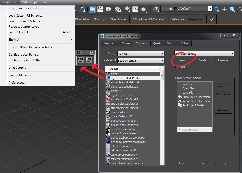
Устанавливаются они достаточно просто, из архива копируются в папку 3ds max вашей версии, затем добавляются в виде кнопок или quad меню.
В главном меню выбираем Customize -> Customize User Interface, во вкладке Category выбирается SoulburnScripts. Кнопкой New создается панель для скриптов и в нее перетягиваются нужные скрипты.
Итак, я опишу те скрипты и настройки которые использую я.
1. AlignViewportToFace, выравнивает вид относительно выделенного полигона.
2. AlignViewportToFace UI. Настройки AlignViewportToFace, рекомендую переключить на create new user view, иначе будет создаваться камера, выравненная относительно полигона.
3. AttachSelectObjects, сливает выбранные объекты в один объект editable poly.
4. AttachSelectObjects UI. Настройки AttachSelectObjects, можно выбрать слитие mesh или spline, или автоматический режим, который у меня не всегда работает.
5. Object Detacher, разъединяет editable poly или mech, создавая отдельные объекты из элементов. Не работает если к объекту добавлен модификатор.
6. Object Detacher UI. Настройки Object Detacher.
8. Image Plane Maker UI, создает плоскость с выбранной текстурой, для выбранного вида, сохраняя пропорции.
9. objectDropper, опускает выбранные объекты на плоскость.
10. objectDropper UI. Настройки objectDropper
11. putpivotUI, служит для выравнивая pivot объекта.
12. SurfaceSnapperUI. При выделении двух объектов, первый выделенный объект возможно расположить на поверхности другого перетягиванием мышкой. В 3ds max 2015 такая функция встроена, так что там он вряд ли вам понадобиться.
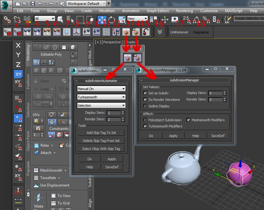
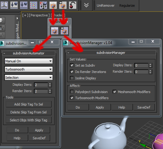
13. subdivisionAutomator, автоматически добавляется turbosmoot модификатор к выделенному объекту или сцене.
14. Subdivisionmanager, позволяет управлять итеракциями модификаторов turbosmoot и mechsmoot. Настройки этих кнопок я вынес отдельно, т. к. после первоначальной настройки они мне не нужны, и настроил я их следующим образом:
Что позволяют делать такие настройки? Во первых добавлять и отключает turbosmooth выбранных объектов, не переходя к модификаторам, во вторых отключать smooth одним кликом, даже если модификатор turbosmooth не является для них общим, затем включать его для них, так же одним кликом, в третьих очень удобно работать с сгруппированными объектами, например если к нескольким объектам добавлен модификатор turbosmooth, а хочется ко всем, достаточно отключить Subdivision, затем включить и группе будет добавлен turbosmooth c одинаковыми интеракциями.
15. getmatFromselectedobject. Помещает материал выбранного объекта в выбранный слот в mateditor. Это все скрипты soulburnscripts, которые использую лично я, хотя я описал не большую часть скриптов и возможно вы для себя найдете еще кучу полезного в этой коллекции.
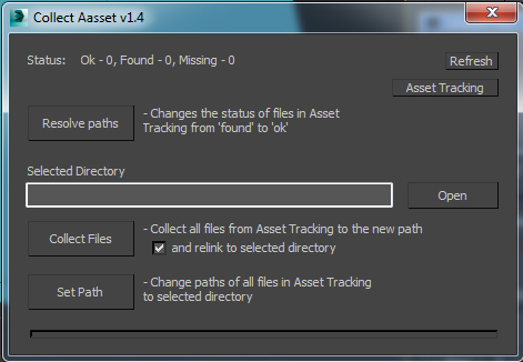
16. Collect aasset, удобная альтернатива максовского resource collector, собирает все текстуры в одну папку и переназначает пути по желанию.
17. Uniremover, скрип для удаления граней, вершин или полигонов, я пользуюсь им для удаления граней или вершин, т. К. он не оставляет вершин после удаления граней и не удаляет все грани при удалении вершин, в отличии от remove.
18. Regularize, делает круг выделенных замкнуто граней.
Я опишу остальные скрипты, которые я добавляю время от время в рабочую среду 3ds max.
1. hoha_changematerialid_v1-1.1, добавляет к выбранным объектам модификатор material и рандомно устанавливает ID в выбранном количестве.
2. 111_randomElementsMatIDs_v0.1, устанавливает рандомно Id каждого элемента в edit poly в выбранном диапозоне.
3. FloorGenerator, генерирует планки паркета в одном меше.
Пара мини-программ.
В отсутствии второго монитора, я использую пару программ для закрепления папок и картинок поверх всех окон, вот они:
DeskPins, программа для закрепления картинок и открытых папок поверх окон.
OnTopReplica, выводит выбранный открытый рисунок поверх окон, имеет ряд удобных функции, таких как обрезании по области или убирание рамки окна.

By:
The Transform gizmos are viewport icons that let you quickly choose an axis or combination of axes when transforming a selection with the mouse.
- Select an object. > Main Toolbar > Click any transform button to display the object's Transform Gizmo icon.
A Transform gizmo appears when one or more objects are selected and one of the transform buttons—Select And Move, Select And Rotate, or Select And Scale—is active on the main toolbar. Each transform type uses a different gizmo. By default, each axis is assigned one of three colors: X is red, Y is green, and Z is blue. The inner corners of the Move gizmo contain plane handles whose edges are assigned the two colors of the related axes; for example, the edges of the XZ plane handle are red and blue. And the Scale gizmo has a central area for uniform scaling, which is surrounded by three plane handles.

From left to right: Move gizmo, Rotate gizmo, Scale gizmo
You choose an axis by first positioning the mouse over any axis of the icon, then dragging the mouse to transform the selection along that axis. When moving an object, you can use the plane handles to perform transforms along any two axes simultaneously. The central area of the Scale gizmo provides, in addition to plane handles for scaling along two axes simultaneously, a uniform-scaling handle at the center. Using a gizmo avoids the need to first specify a transform axis or axes on the Axis Constraints toolbar, and also lets you switch quickly and easily among different transform axes and planes.
When you position the mouse over any axis, it turns yellow to indicate that it’s active. Similarly, position the mouse over one of the plane handles, and both associated axes turn yellow. You can now drag the selection along the indicated axis or axes. Doing so changes the Axis Constraints toolbar "Restrict to . " setting. This means that you can then drag anywhere on the object and the axis constraint will remain active. The axis constraint remains active for that transform for all objects, even if you switch to a different transform and then back again.
Interface
Customize menu Customize User Interface dialog Colors panel Gizmos Element Active Transform Gizmo and Transform Gizmo X/Y/Z.
Enable/disable Transform Gizmo
Customize menu Preferences Gizmos Preferences On checkbox.
Note: When you turn off the Transform gizmo in Preferences, the standard axis tripod appears instead. To toggle display of either the gizmo or the tripod, use Views menu Show Transform Gizmo. (If using the enhanced menu, it's Scene Configure Views Show Transform Gizmo.)
There are additional controls for each gizmo on the Gizmos Preferences panel of the Preferences dialog.
By:
The Transform gizmos are viewport icons that let you quickly choose an axis or combination of axes when transforming a selection with the mouse.
- Select an object. > Main Toolbar > Click any transform button to display the object's Transform Gizmo icon.
A Transform gizmo appears when one or more objects are selected and one of the transform buttons—Select And Move, Select And Rotate, or Select And Scale—is active on the main toolbar. Each transform type uses a different gizmo. By default, each axis is assigned one of three colors: X is red, Y is green, and Z is blue. The inner corners of the Move gizmo contain plane handles whose edges are assigned the two colors of the related axes; for example, the edges of the XZ plane handle are red and blue. And the Scale gizmo has a central area for uniform scaling, which is surrounded by three plane handles.

From left to right: Move gizmo, Rotate gizmo, Scale gizmo
You choose an axis by first positioning the mouse over any axis of the icon, then dragging the mouse to transform the selection along that axis. When moving an object, you can use the plane handles to perform transforms along any two axes simultaneously. The central area of the Scale gizmo provides, in addition to plane handles for scaling along two axes simultaneously, a uniform-scaling handle at the center. Using a gizmo avoids the need to first specify a transform axis or axes on the Axis Constraints toolbar, and also lets you switch quickly and easily among different transform axes and planes.
When you position the mouse over any axis, it turns yellow to indicate that it’s active. Similarly, position the mouse over one of the plane handles, and both associated axes turn yellow. You can now drag the selection along the indicated axis or axes. Doing so changes the Axis Constraints toolbar "Restrict to . " setting. This means that you can then drag anywhere on the object and the axis constraint will remain active. The axis constraint remains active for that transform for all objects, even if you switch to a different transform and then back again.
Procedures
Example: To explore use of the transform gizmo:
The transform gizmo appears at the center of the sphere. Because the default axis constraint on the Axis Constraints toolbar is XY Plane, the X and Y shafts of the transform gizmo are yellow (active), while the Z shaft is blue.
The Z shaft turns yellow, the X and Y shafts turn red and green, respectively, and the sphere moves along the Z axis.
The Y shaft turns yellow, and the sphere moves along only the Y axis.
The sphere moves along the XY plane.
The sphere moves along the XY plane.
The sphere moves along only the X axis.
Experiment with other transformations, such as rotation and scale. Try different reference coordinate systems. Experiment with sub-object transformations.
Scale Gizmo
The Scale gizmo includes plane handles and scaling feedback through the stretching of the gizmo itself.
The plane handles let you perform uniform and non-uniform scaling without changing your selection on the main toolbar:
-
To perform Uniform scaling, drag in the center of the gizmo.

The Transform gizmo with Uniform scaling selected.

Top: The Scale gizmo with the YZ plane handle selected
Bottom: Non-uniform scaling on the YZ plane
The Scale gizmo provides feedback by changing its size and shape; in the case of a uniform scale operation, it will grow or shrink as the mouse moves, and during non-uniform scaling, the gizmo will stretch and deform while dragging. However, once the mouse button is released, the gizmo returns to its original size and shape.
You can adjust settings for the Scale gizmo on the Gizmos Preferences panel of the Preferences dialog
Interface
Customize menu Customize User Interface dialog Colors panel Gizmos Element Active Transform Gizmo and Transform Gizmo X/Y/Z.
Enable/disable Transform Gizmo
Customize menu Preferences Gizmos Preferences On checkbox.
Note: When you turn off the Transform gizmo in Preferences, the standard axis tripod appears instead. To toggle display of either the gizmo or the tripod, use Views menu Show Transform Gizmo. (If using the enhanced menu, it's Scene Configure Views Show Transform Gizmo.)
There are additional controls for each gizmo on the Gizmos Preferences panel of the Preferences dialog.
Procedures
Example: To explore use of the transform gizmo:
The transform gizmo appears at the center of the sphere. Because the default axis constraint on the Axis Constraints toolbar is XY Plane, the X and Y shafts of the transform gizmo are yellow (active), while the Z shaft is blue.
The Z shaft turns yellow, the X and Y shafts turn red and green, respectively, and the sphere moves along the Z axis.
The Y shaft turns yellow, and the sphere moves along only the Y axis.
The sphere moves along the XY plane.
The sphere moves along the XY plane.
The sphere moves along only the X axis.
Experiment with other transformations, such as rotation and scale. Try different reference coordinate systems. Experiment with sub-object transformations.
Move Gizmo
The Move gizmo includes plane handles, and the option to use a center box handle.
You can select any of the axis handles to constrain movement to that axis. In addition, the plane handles allow you to constrain movement to the XY, YZ, or XZ planes. The selection hotspot is within the square formed by the plane handles. You can change the size and offset of the handles and other settings on the Gizmos Preferences panel of the Preferences dialog.

The Move gizmo with the YZ axes selected.
You can constrain translation to the viewport plane by dragging the center box. To disable this optional control, turn off Move In Screen Space.

Axis Tripods
When no transform tool is active and you select one or more objects, axis tripods appear in the viewport.

The axis tripod appears when the transform gizmo is inactive.
Each axis tripod consists of three lines, labeled X, Y, and Z, and shows you three things:
- The orientation of the tripod reveals the orientation of the current reference coordinate system.
- The location of the junction of the three axis lines shows where the current transform center is.
- The highlighted red axis lines show the current axis constraints.
Notes
Using a Transform gizmo sets the default axis constraint to the last axis or plane you used.
If Lock Selection Set is on, you can drag anywhere in the viewport to transform the object. Dragging an axis, however, still applies the constraint along that axis.
Axis Tripods
When no transform tool is active and you select one or more objects, axis tripods appear in the viewport.

The axis tripod appears when the transform gizmo is inactive.
Each axis tripod consists of three lines, labeled X, Y, and Z, and shows you three things:
- The orientation of the tripod reveals the orientation of the current reference coordinate system.
- The location of the junction of the three axis lines shows where the current transform center is.
- The highlighted red axis lines show the current axis constraints.
Scale Gizmo
The Scale gizmo includes plane handles and scaling feedback through the stretching of the gizmo itself.
The plane handles let you perform uniform and non-uniform scaling without changing your selection on the main toolbar:
-
To perform Uniform scaling, drag in the center of the gizmo.

The Transform gizmo with Uniform scaling selected.

Top: The Scale gizmo with the YZ plane handle selected
Bottom: Non-uniform scaling on the YZ plane
The Scale gizmo provides feedback by changing its size and shape; in the case of a uniform scale operation, it will grow or shrink as the mouse moves, and during non-uniform scaling, the gizmo will stretch and deform while dragging. However, once the mouse button is released, the gizmo returns to its original size and shape.
You can adjust settings for the Scale gizmo on the Gizmos Preferences panel of the Preferences dialog
Move Gizmo
The Move gizmo includes plane handles, and the option to use a center box handle.
You can select any of the axis handles to constrain movement to that axis. In addition, the plane handles allow you to constrain movement to the XY, YZ, or XZ planes. The selection hotspot is within the square formed by the plane handles. You can change the size and offset of the handles and other settings on the Gizmos Preferences panel of the Preferences dialog.

The Move gizmo with the YZ axes selected.
You can constrain translation to the viewport plane by dragging the center box. To disable this optional control, turn off Move In Screen Space.

Rotate Gizmo
The Rotate gizmo is built around the concept of a virtual trackball. You can rotate an object freely, about the X, Y, or Z axis, or about an axis perpendicular to the viewport.

The axis handles are circles around the trackball. Drag anywhere on one of them to rotate the object about that axis. As you rotate about the X, Y, or Z axis a transparent slice provides a visual representation of the direction and amount of rotation. If you rotate more than 360°, the slice overlaps and the shading becomes increasingly opaque. 3ds Max also displays numerical data to indicate a precise rotational measurement.

In addition to XYZ rotation, you can also use free rotation or the viewport handle to rotate objects.
Drag inside the Rotate gizmo (or the outer edge of the gizmo) to perform free rotation. Rotation should behave as if you were actually spinning the trackball.
The outermost circle around the Rotate gizmo is the Screen handle, which lets you rotate the object on a plane parallel to the viewport.
You can adjust settings for the Rotate gizmo on the Gizmos Preferences panel of the Preferences dialog
Notes
Using a Transform gizmo sets the default axis constraint to the last axis or plane you used.
If Lock Selection Set is on, you can drag anywhere in the viewport to transform the object. Dragging an axis, however, still applies the constraint along that axis.
Scale Gizmo
The Scale gizmo includes plane handles and scaling feedback through the stretching of the gizmo itself.
The plane handles let you perform uniform and non-uniform scaling without changing your selection on the main toolbar:
-
To perform Uniform scaling, drag in the center of the gizmo.

The Transform gizmo with Uniform scaling selected.

Top: The Scale gizmo with the YZ plane handle selected
Bottom: Non-uniform scaling on the YZ plane
The Scale gizmo provides feedback by changing its size and shape; in the case of a uniform scale operation, it will grow or shrink as the mouse moves, and during non-uniform scaling, the gizmo will stretch and deform while dragging. However, once the mouse button is released, the gizmo returns to its original size and shape.
You can adjust settings for the Scale gizmo on the Gizmos Preferences panel of the Preferences dialog
Procedures
Example: To explore use of the transform gizmo:
The transform gizmo appears at the center of the sphere. Because the default axis constraint on the Axis Constraints toolbar is XY Plane, the X and Y shafts of the transform gizmo are yellow (active), while the Z shaft is blue.
The Z shaft turns yellow, the X and Y shafts turn red and green, respectively, and the sphere moves along the Z axis.
The Y shaft turns yellow, and the sphere moves along only the Y axis.
The sphere moves along the XY plane.
The sphere moves along the XY plane.
The sphere moves along only the X axis.
Experiment with other transformations, such as rotation and scale. Try different reference coordinate systems. Experiment with sub-object transformations.
Move Gizmo
The Move gizmo includes plane handles, and the option to use a center box handle.
You can select any of the axis handles to constrain movement to that axis. In addition, the plane handles allow you to constrain movement to the XY, YZ, or XZ planes. The selection hotspot is within the square formed by the plane handles. You can change the size and offset of the handles and other settings on the Gizmos Preferences panel of the Preferences dialog.

The Move gizmo with the YZ axes selected.
You can constrain translation to the viewport plane by dragging the center box. To disable this optional control, turn off Move In Screen Space.

Rotate Gizmo
The Rotate gizmo is built around the concept of a virtual trackball. You can rotate an object freely, about the X, Y, or Z axis, or about an axis perpendicular to the viewport.

The axis handles are circles around the trackball. Drag anywhere on one of them to rotate the object about that axis. As you rotate about the X, Y, or Z axis a transparent slice provides a visual representation of the direction and amount of rotation. If you rotate more than 360°, the slice overlaps and the shading becomes increasingly opaque. 3ds Max also displays numerical data to indicate a precise rotational measurement.

In addition to XYZ rotation, you can also use free rotation or the viewport handle to rotate objects.
Drag inside the Rotate gizmo (or the outer edge of the gizmo) to perform free rotation. Rotation should behave as if you were actually spinning the trackball.
The outermost circle around the Rotate gizmo is the Screen handle, which lets you rotate the object on a plane parallel to the viewport.
You can adjust settings for the Rotate gizmo on the Gizmos Preferences panel of the Preferences dialog
Notes
Using a Transform gizmo sets the default axis constraint to the last axis or plane you used.
If Lock Selection Set is on, you can drag anywhere in the viewport to transform the object. Dragging an axis, however, still applies the constraint along that axis.
Interface
Customize menu Customize User Interface dialog Colors panel Gizmos Element Active Transform Gizmo and Transform Gizmo X/Y/Z.
Enable/disable Transform Gizmo
Customize menu Preferences Gizmos Preferences On checkbox.
Note: When you turn off the Transform gizmo in Preferences, the standard axis tripod appears instead. To toggle display of either the gizmo or the tripod, use Views menu Show Transform Gizmo. (If using the Alt menu, it's Scene Configure Views Show Transform Gizmo.)
There are additional controls for each gizmo on the Gizmos Preferences panel of the Preferences dialog.
By:
The Transform gizmos are viewport icons that let you quickly choose an axis or combination of axes when transforming a selection with the mouse.
- Select an object. > Main Toolbar > Click any transform button to display the object's Transform Gizmo icon.
A Transform gizmo appears when one or more objects are selected and one of the transform buttons—Select And Move, Select And Rotate, or Select And Scale—is active on the main toolbar. Each transform type uses a different gizmo. By default, each axis is assigned one of three colors: X is red, Y is green, and Z is blue. The inner corners of the Move gizmo contain plane handles whose edges are assigned the two colors of the related axes; for example, the edges of the XZ plane handle are red and blue. And the Scale gizmo has a central area for uniform scaling, which is surrounded by three plane handles.

From left to right: Move gizmo, Rotate gizmo, Scale gizmo
You choose an axis by first positioning the mouse over any axis of the icon, then dragging the mouse to transform the selection along that axis. When moving an object, you can use the plane handles to perform transforms along any two axes simultaneously. The central area of the Scale gizmo provides, in addition to plane handles for scaling along two axes simultaneously, a uniform-scaling handle at the center. Using a gizmo avoids the need to first specify a transform axis or axes on the Axis Constraints toolbar, and also lets you switch quickly and easily among different transform axes and planes.
When you position the mouse over any axis, it turns yellow to indicate that it’s active. Similarly, position the mouse over one of the plane handles, and both associated axes turn yellow. You can now drag the selection along the indicated axis or axes. Doing so changes the Axis Constraints toolbar "Restrict to . " setting. This means that you can then drag anywhere on the object and the axis constraint will remain active. The axis constraint remains active for that transform for all objects, even if you switch to a different transform and then back again.
Читайте также: