
Ds18b20 подключение к esp8266 arduino ide
Для того чтобы в помещении было комфортно, а в теплице вырос хороший урожай, нужно правильно выбирать и поддерживать температуру воздуха. Датчик DS18B20 – хорошее решение для определения температуры окружающей среды.
CSS File
Copy the following styles to your style.css file.
2. Filesystem Uploader Plugin
To upload the HTML, CSS, and JavaScript files to the ESP8266 flash memory (LittleFS), we’ll use a plugin for Arduino IDE: LittleFS Filesystem uploader. Follow the next tutorial to install the filesystem uploader plugin:
If you’re using VS Code with the PlatformIO extension, read the following tutorial to learn how to upload files to the filesystem:
Датчик DS18B20
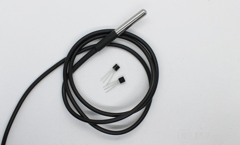
DS18B20 — это популярный цифровой датчик по измерению температуры. Изготавливается в разных вариациях корпуса, особенно интересен во влагозащищённом корпусе, который значительно расширяет область применения датчика. Применяется в различных системах мониторинга температуры или узлах оборудования. Диапазон измерения температуры составляет от -55 до +125 градусов Цельсия. Погрешность датчика составляет 0.5 градуса. Датчик подключается по 1WIRE шине, поэтому возможно подключения нескольких датчиков на один пин.
MQTT Broker

To use MQTT, you need a broker. We’ll be using Mosquitto broker installed on a Raspberry Pi. Read How to Install Mosquitto Broker on Raspberry Pi.
You can use any other MQTT broker, including a cloud MQTT broker. We’ll show you how to do that in the code later on.
If you’re not familiar with MQTT make sure you read our introductory tutorial: What is MQTT and How It Works.
Installing Libraries (VS Code + PlatformIO)
If you’re programming the ESP8266 using PlatformIO, you should add the following lines on the platformio.ini file to include the libraries (also change the Serial Monitor speed to 115200):
Подключение датчика
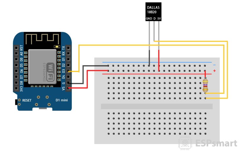
Подключите датчики согласно схеме ниже. Для этого подсоединяем питание 5V и GND, подтягиваем питание к ПИН D3 через резистор 4.7 кОм и подключаем ногу DATA датчика. При подключении влагозащищенного датчика: красный – питание, черный – земля, а желтый/белый/синий – сигнал (DATA).
Примечание. Определите правильно ноги датчика при подключении. На схеме подключения представлена сторона датчика на которой нанесена модель датчика.
JavaScript File (creating the charts)
Copy the following to the script.js file. Here’s a list of what this code does:
How the code works
Let’s take a look at the code and see how it works to send readings to the client using server-sent events.
Including Libraries
The OneWire and DallasTemperature libraries are needed to interface with the DS18B20 temperature sensors.
The ESP8266WiFi , ESPAsyncWebServer and ESPsyncTCP libraries are used to create the web server.
The HTML, CSS, and JavaScript files to build the web page are saved on the ESP8266 filesystem (LittleFS). So, we also need to include the LitteFS library.
You also need to include the Arduino_JSON library to make it easier to handle JSON strings.
Network Credentials
Insert your network credentials in the following variables, so that the ESP8266 can connect to your local network using Wi-Fi.
AsyncWebServer and AsyncEventSource
Create an AsyncWebServer object on port 80.
The following line creates a new event source on /events .
Declaring Variables
The readings variable is a JSON variable to hold the sensor readings in JSON format.
The lastTime and the timerDelay variables will be used to update sensor readings every X number of seconds. As an example, we’ll get new sensor readings every 30 seconds (30000 milliseconds). You can change that delay time in the timerDelay variable.
DS18B20 Sensors
The DS18B20 temperature sensors are connected to GPIO 4 (D2).
Setup a oneWire instance to communicate with OneWire devices (DS18B20):
Pass our oneWire reference to Dallas Temperature sensor
Insert the addresses of your DS18B20 Sensors in the following lines (check this section if you don’t have the addresses of your sensors):
Get DS18B20 Readings
To get readings from the DS18B20 temperature sensors, first, you need to call the requesTemperatures() method on the sensors object. Then, use the getTempC() function and pass as argument the address of the sensor you want to get the temperature—this gets the temperature in celsius degrees.
Note: if you want to get the temperature in Fahrenheit degrees, use the getTemF() function instead.
Finally, save the readings in a JSON string ( jsonString variable) and return that variable.
Initialize LittleFS
The initLittleFS() function initializes the LittleFS filesystem:
Intialize WiFi
The initWiFi() function initializes Wi-Fi and prints the IP address on the Serial Monitor.
setup()
In the setup() , initialize the Serial Monitor, Wi-Fi and filesystem.
Handle Requests
When you access the ESP8266 IP address on the root / URL, send the text that is stored on the index.html file to build the web page.
Serve the other static files requested by the client (style.css and script.js).
When you receive a request on the /readings URL, reset the timer—this way, the if statement in the loop() will be true and the ESP8266 will send new readings via SSE.
We send a response with OK , so that we know on the client-side that the ESP8266 received the request.
Server Event Source
Set up the event source on the server.
Finally, start the server.
In the loop() , send events to the browser with the newest sensor readings to update the web page every 30 seconds.
Use the send() method on the events object and pass as an argument the content you want to send and the name of the event. In this case, we want to send the JSON string returned by the getSensorReadings() function. The name of the events is new_readings .
Подключение библиотеки
Для работы с датчиком DS18B20 добавим в Arduino IDE библиотеку. Открываем менеджер библиотек и находим библиотеку DallasTemperature by Miles Burton, Tem Newsome, Guil Barros, Rob Tillaart.

Artwork by Павел Бондаренко
ESP8266 может работать в двух режимах: в режиме интерпретатора AT-команд или в режиме самостоятельного микроконтроллера с wifi модулем. Работу ESP8266 в режиме интерпретатора AT-команд я рассматривал в предыдущей статье, эта же статья рассматривает работу ESP8266 в качестве самостоятельного микроконтроллера.
Способов программирования ESP8266 опять же два, первый - это программирование с помощью ESP8266 фреймворка для Arduino IDE, второй - это программирование через esp-open-sdk. В первом случае мы можем использовать готовые библиотеки Arduino, во втором случае вы можем положиться только на функционал SDK и свой собственный код.
В этой статье мне хотелось бы рассмотреть программирование ESP8266 с помощью ESP8266 фреймворка для Arduino IDE. Данная тема решает широкий спектр задач обеспечения радиоканалом разного рода датчиков и простых устройств управления нагрузкой.
В качестве примера в статье рассматривается пошаговое написание прошивки для температурного логера на датчиках DHT11 и DS18B20. Первый датчик используется для определения комнатной температуры и влажности, второй используется для определения уличной температуры. Я статье используется плата ModeMCU ESP8266, т.к. там есть автозагузка прошивки, но в принципе может быть использована любая другая плата на модуле ESP12E/ESP12F. Данные модули оснащены флеш-памятью на 4 мегабайта, что позволяет забыть о жёсткой оптимизации размера прошивки, когда борьба идёт за каждый байт.
При работе с ESP8266 есть выбор для использования его совместно с "облаками", собственным внешним сайтом, собственном сервером расположенным в интросети или автономной работой ESP826, когда веб-сервер запускается на самом ESP8266.
-
Ссылки на полезные ресурсы и документацию:
- ESP8266 фреймворк для Arduino IDE
- Документация на библиотеку ESP8266WIFI
- Документация на Arduino библиотеку WiFi library
I. Начало работы с ESP8266 фреймворком для Arduino IDE
II. Работа с библиотекой ESP8266WIFI
- Установка WiFi соединения
- Использование режима энергосбережения DeepSleep
- Класс WiFiClient, получение web-страницы от сервера на OpenWRT и отправка данных через GET запрос
- Отправка на web-сервер данных с датчика DHT11 через GET запрос
- Добавление датчика DS18B20
- Вывод показаний датчиков через веб-интерфейс
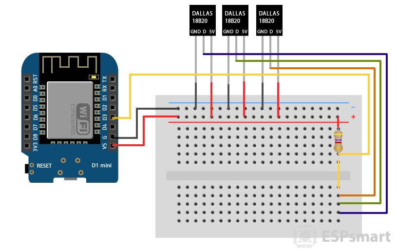
3) Подключение датчика DS18B20 к ESP8266
Вторым датчиком который мы подключим ESP8266, будет DS18B20. Схема его подключения к NodeMCU ESP8266 показана ниже:
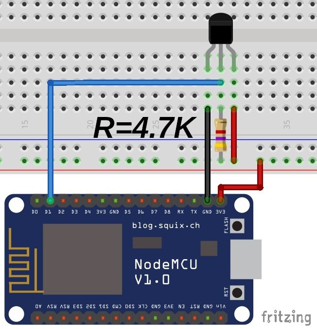
Здесь, так же как и в случае с DHT11, Data pin подтягивается к шине питания через резистор номиналом 4.7КОм.
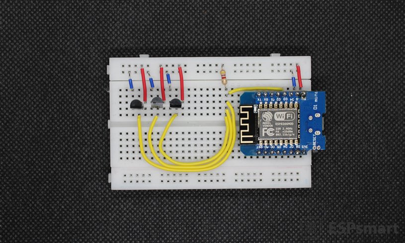
Подключаем датчик к плате NodeMCU, скачиваем библиотеку "OneWire" и открываем пример DS18x20_Temperature.
В примере правим строку:
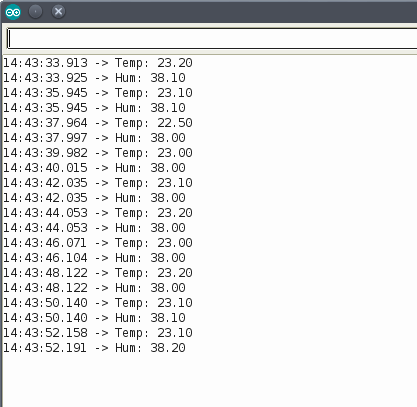
также можно еще скорость UART поднять до значения 115200
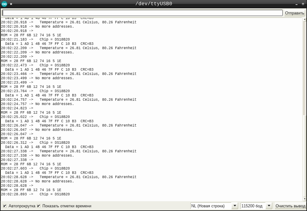
Если все было сделано правильно, то после компиляции примера и загрузки прошивки в микроконтроллер, мы получим следующий лог работы в мониторе последовательного порта:
Подключение нескольких датчиков DS18B20 к Arduino
Подключение довольно простое.
Начните с подключения всех датчиков DS18B20 параллельно, то есть объединения всех выводов VDD, выводов GND и сигнальных выводов. Затем подключите шину VDD к выходу 5V на Arduino, GND к выводу земли Arduino, и подключите сигнальные выводы к цифровому выводу 2 на Arduino.
Затем, чтобы обеспечить стабильную передачу данных, вам нужно добавить один подтягивающий резистор 4,7 кОм для всей шины между сигнальными выводами и выводами питания (внутренние подтягивающие резисторы на ардуино не работают).

Рисунок 1 – Подключение нескольких датчиков температуры DS18B20 с Arduino
1. Install ESP8266 Board in Arduino IDE
We’ll program the ESP8266 using Arduino IDE. So, you must have the ESP8266 add-on installed. Follow the next tutorial if you haven’t already:
If you want to use VS Code with the PlatformIO extension, follow the next tutorial instead to learn how to program the ESP8266:
4) Установка WiFi соединения
Теперь, когда у нас есть данные, которые нужно куда-то передавать, самое время разобраться с библиотекой ESP8266WIFI, с помощью которой мы будем это делать.
Библиотека ESP8266WIFI имеет схожий API c библиотекой Arduino WIFI.
Опираясь на эту информацию, начинаем писать код.
В составе библиотеки ESP8266WIFI имеется 17 примеров, среди которых имеется пример для сканирования доступных точек доступа: WIFIScan. Я переписал его на свой манер:
Результат работы программы выглядит так:

Действие программы соответствует AT-команде CWLAP, её можно свернуть в функцию с названием, скажем list_wifi(). На базе этой функции можно написать другую, которая будет искать определенную точку доступа. Можно ее будет также наделить полезным свойством, возвращать в случае обнаружения заданной точки доступа уровень ее сигнала rssi. Т.о. получим функцию двойного назначения get_rssi():
Дело осталось за малым, установить соединение с точной доступа. У меня это получилось так:
Getting the DS18B20 Sensors’ Addresses
Each DS18B20 temperature sensor has an assigned serial number. First, you need to find that number to label each sensor accordingly. You need to do this so that later you know from which sensor you’re reading the temperature.
Upload the following code to the ESP8266. Make sure you have the right board and COM port selected.
The HTML file for this project is very simple. It includes the JavaScript Highcharts library in the head of the HTML file:
There is a section with the id chart-temperature where we’ll render our chart later on.
8) Добавление датчика DS18B20
Теперь нужно добавить опрос датчика DS18B20, и передачу его данных на web-сервер. Для этого я добавил в программу код из примера "DS18x20_Temperature" библиотеки OneWire. Этот пример поддерживает датчики: DS18S20, DS18B20, DS1822. Я не стал его упрощать затачивая конкретно под свой DS18B20, а оставил как есть:
Теперь показания датчиков выглядят следующим образом:
Здесь ds18b20 снимает показания по одну сторону окна, а dht11 - по другую.
Объяснение кода
Скетч начинается с включения библиотек, объявления вывода, к которому подключена шина датчиков, и создания объекта библиотеки DallasTemperature .
В настроечной части кода мы сначала вызываем функцию begin() . Она инициализирует шину и обнаруживает все DS18B20, присутствующие на ней. Затем каждому датчику присваивается индекс и устанавливается разрешение в 12 бит.
Затем мы вызываем функцию getDeviceCount() , чтобы получить количество устройств, найденных на шине.
Plot Temperatures
We’ve created the plotTemperature() function that accepts as an argument a JSON object with the temperature readings we want to plot.
First, we get the keys of our JSON object and save them on the keys variable. This allows us to go through all the keys in the object.
The keys variable will be an array with all the keys in the JSON object. In our case:
This works if you have a JSON object with a different number of keys or with different keys. Then, we’ll go through all the keys ( keys.length() ) to plot each of its value in the chart.
The x value for the chart is the timestamp.
The key variable holds the current key in the loop. The first time we go through the loop, the key variable is “sensor1” .
Then, we get the value of the key ( jsonValueDs18b20 подключение к esp8266 arduino ide ) and save it as a number in the y variable.
Our chart has multiple series (index starts at 0). We can access the first series in the
temperature chart using: chartT.series[0] , which corresponds to chartT.series[i] the first time we go through the loop.
First, we check the series data length:
- If the series has more than 40 points: append and shift a new point;
- Or if the series has less than 40 points: append a new point.
To add a new point use the addPoint() method that accepts the following arguments:
- The value to be plotted. If it is a single number, a point with that y value is
appended to the series. If it is an array, it will be interpreted as x and y values. In our case, we pass an array with the x and y values; - Redraw option (boolean): set to true to redraw the chart after the point is added.
- Shift option (boolean): If true , a point is shifted off the start of the series as one is appended to the end. When the chart length is bigger than 40, we set the shift option to true .
- withEvent option (boolean): Used internally to fire the series addPoint event—learn more here.
So, to add a point to the chart, we use the next lines:
Demonstration
Open your browser and type the ESP8266 IP address. You should get access to the web page that shows the sensor readings. Wait some time until it gathers some data points.

You can select a point to see its value and timestamp.

Get Readings
When you access the web page for the first time, we’ll request the server to get the current sensor readings. Otherwise, we would have to wait for new sensor readings to arrive (via Server-Sent Events), which can take some time depending on the interval that you set on the server.
Add an event listener that calls the getReadings function when the web page loads.
The window object represents an open window in a browser. The addEventListener() method sets up a function to be called when a certain event happens. In this case, we’ll call the getReadings function when the page loads ( ‘load’ ) to get the current sensor readings.
- readyState = 4 means that the request finished and the response is ready;
- status = 200 means “OK”
In our case, we’ll just log the ESP response (an “OK” message). So, the request should look something like this:
Files Saved on the Filesystem (LittleFS)
To keep our project better organized and easier to understand, we’ll save the HTML, CSS, and JavaScript files to build the web page on the board’s filesystem (LittleFS).
Learn more about using LittleFS with the ESP8266, you can read:
How the Code Works
The following section imports all the required libraries.
Include your network credentials on the following lines.
Insert the Raspberry Pi IP address, so that the ESP8266 connects to your broker.
If you’re using a cloud MQTT broker, insert the broker domain name, for example:
Define the MQTT port.
We’ll publish the temperature on the esp/ds18b20/temperature topic. If you want to change the topic, change it on the following line.
You can create more topics if you want.
Setup your DS18B20 on the following lines. In our case, it is connected to GPIO 4 . You can connect it to any other GPIO.
The temp variable will hold the temperature value from the DS18B20 temperature sensor.
Create an AsyncMqttClient object called mqttClient to handle the MQTT client and timers to reconnect to your MQTT broker and router when it disconnects.
Then, create some auxiliary timer variables to publish the readings every 10 seconds. You can change the delay time on the interval variable.
Publishing to topics
To publish a message on an MQTT topic, use the next line:
If you would like to publish more readings on different topics, you can duplicate this previous line the loop() .
Basically, use the publish() method on the mqttClient object to publish data on a topic. The publish() method accepts the following arguments, in order:
- MQTT topic (const char*)
- QoS (uint8_t): quality of service – it can be 0, 1 or 2
- retain flag (bool): retain flag
- payload (const char*)
The QoS (quality of service) is a way to guarantee that the message is delivered. It can be one of the following levels:
- 0: the message will be delivered once or not at all. The message is not acknowledged. There is no possibility of duplicated messages;
- 1: the message will be delivered at least once, but may be delivered more than once;
- 2: the message is always delivered exactly once;
Preparing Node-RED Dashboard
The ESP8266 is publishing temperature readings every 10 seconds on the esp/ds18b20/temperature topic. Now, you can use any dashboard that supports MQTT or any other device that supports MQTT to subscribe to that topic and receive the readings.
As an example, we’ll create a simple flow using Node-RED to subscribe to that topic and display the readings on a gauge or chart.
If you don’t have Node-RED installed, follow the next tutorials:
Having Node-RED running on your Raspberry Pi, go to your Raspberry Pi IP address followed by :1880.
The Node-RED interface should open. Drag an MQTT in node, a chart node and a gauge node to the flow.

Click the MQTT node and edit its properties as follows:

The Server field refers to the MQTT broker. In our case, the MQTT broker is the Raspberry Pi, so it is set to localhost:1883. If you’re using a Cloud MQTT broker, you should change that field. Insert the topic you want to be subscribed to and the QoS.
Set the following properties for the gauge node.

Edit the chart node as follows:

Wire your nodes as shown below:

Finally, deploy your flow (press the button on the upper right corner).
Alternatively, you can go to Menu > Import and copy the following to your Clipboard to create your Node-RED flow.
Arduino Sketch
Copy the following code to your Arduino IDE or to the main.cpp file if you’re using PlatformIO.
Wrapping Up
MQTT is a great communication protocol to exchange small amounts of data between devices. In this tutorial you’ve learned how to publish DS18B20 temperature readings with the ESP8266 on an MQTT topic. Then, you can use any device or home automation platform to subscribe to that topic and receive the readings.
Instead of a DS18B20, you can use any a different sensor:
We hope you’ve found this tutorial useful. If you want to learn more about the ESP8266, take a look at our resources:
This project shows how to build a web server with the ESP8266 NodeMCU board to plot sensor readings in charts with multiple series. As an example, we’ll plot sensor readings from four different DS18B20 temperature sensors on the same chart. You can modify the project to plot any other data. To build the charts, we’ll use the Highcharts JavaScript library.

We have a similar tutorial for the ESP32 board:
1) Установка ESP8266 фреймворка для Arduino IDE
Действуя в соответствии с этой инструкцией, прописываем в настройках Arduino IDE адрес репозитория "http://arduino.esp8266.com/stable/package_esp8266com_index.json":
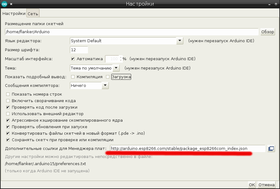
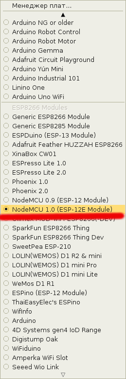
В менеджере плат устанавливаем пакет поддержки плат esp8266:
После установки пакета поддержки esp8266, выставляем в настройках свою плату, в моем случае это nodemcu на модуле esp12e, а настройки платы можно оставить по умолчанию:
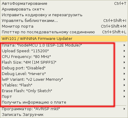
Теперь подключаем плату NodeMCU к компьютеру, выбираем последовательный порт в Arduino IDE, находим в примерах для ESP8266 тестовый скетч "Blink", компилируем, загружаем и наслаждаемся ровным миганием синего светодиода:
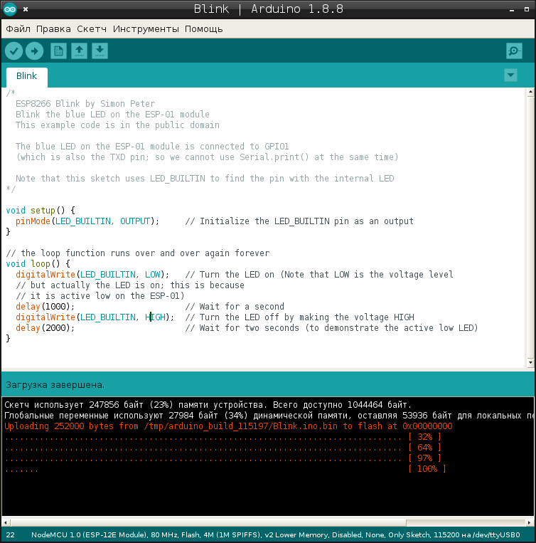
Прошивка занимает почти четверь мегабайта, а процесс прошивки занимает примерно секунд двадцать. Если вы не горите желанием написать свою реализацию TCP/IP стека, то стоит принять это как данность.
Значение константы LED_BUILTIN определенно в файле ~/.arduino15/packages/esp8266/hardware/esp8266/2.4.2/variants/nodemcu/pins_arduino.h:
Т.е. LED_BUILTIN это GPIO_16. Если мы хотим помигать светодиодом который установлен на модуле ESP12E, то приведем скетч к следующему виду:
3. Installing Libraries
To build this project, you need to install the following libraries:
-
(Arduino Library Manager); (Arduino Library Manager); (Arduino Library Manager) (.zip folder); (.zip folder).
You can install the first two libraries using the Arduino Library Manager. Go to Sketch > Include Library > Manage Libraries and search for the library name.
The ESPAsyncWebServer and AsynTCP libraries aren’t available to install through the Arduino Library Manager, so you need to copy the library files to the Arduino Installation Libraries folder. Alternatively, in your Arduino IDE, you can go to Sketch > Include Library > Add .zip Library and select the libraries you’ve just downloaded.
Project Overview
This project will build a web server with the ESP8266 NodeMCU board that displays temperature readings from four DS18B20 temperature sensors on the same chart—chart with multiple series. The chart displays a maximum of 40 data points for each series, and new readings are added every 30 seconds. You can change these values in your code.

Объяснение кода
Как обычно, скетч начинается с включения библиотек, объявления вывода, к которому подключена шина датчиков, и создания объекта библиотеки DallasTemperature .
Далее мы вводим адреса, которые были найдены ранее для каждого датчика температуры. В нашем случае имеем следующее.
Во фрагменте настройки мы инициализируем библиотеку путем вызова функции begin() и инициализируем последовательную связь с ПК.
В цикле мы просто посылаем команду всем датчикам для преобразования температуры, используя функцию requestTemperatures() .
Затем, чтобы напечатать температуру датчика, мы вызываем пользовательскую функцию printTemperature(DeviceAddress deviceAddress) , для которой deviceAddress передается в качестве параметра.
Ясен пень тоже самое, но без функций и лишних печатей. Вы этим уроком что хотели преподнести? Как функции работают или как датчики подключать. Уроки для начинающих? Надо думать как начинающий. Нахрена туда пихать лишнее. Кое как разобрался в вашей писанине. Проще надо быть и люди потянутся.
Что именно усложнено? Какие циклы?
Вы переписали всё то же самое, но без отдельной функции печати температуры в градусах Цельсия и Фаренгейта с символами градусов '°'.
OneWire oneWire(ONE_WIRE_BUS);
DallasTemperature sensors(&oneWire);
void setup(void)
Serial.begin(115200);
sensors.begin();
>
void loop(void)
sensors.requestTemperatures();
Serial.print("температура");
Serial.print(sensors.getTempC(sensor1));
Serial.print("температура");
Serial.print(sensors.getTempC(sensor2));
Serial.print("температура");
Serial.print(sensors.getTempC(sensor3));
delay(1000);
>
И всё. Чё усложнять?
Здравствуйте. Подскажите, пожалуйста, в каком порядке датчикам присваиваются индексы? Могут ли одни и те же датчики получать разные индексы? Спасибо.
DS18B20 Temperature Sensor
The DS18B20 temperature sensor is a one-wire digital temperature sensor. This means that it just requires one data line to communicate with your microcontroller.

Each sensor has a unique 64-bit serial number, which means you can connect multiple sensors to the same GPIO—as we’ll do in this tutorial. Learn more about the DS18B20 temperature sensor:
Server-Sent Events
The readings are updated automatically on the web page using Server-Sent Events (SSE).

To learn more about SSE with the ESP8266, you can read:
Project Overview
The following diagram shows a high-level overview of the project we’ll build.

- The ESP8266 requests temperature readings from the DS18B20 sensor. The readings are published in the esp/ds18b20/temperature topic;
- Node-RED is subscribed to the esp/ds18b20/temperature topic. So, it receives the DS18B20 temperature readings and displays the readings in a gauge/chart;
- You can receive the readings in any other platform that supports MQTT and handle the readings as you want.
9) Вывод показаний датчиков через веб-интерфейс
GCI скрипт для вывода лога измерений получился таким:
Он довольно простой. Второй скрипт будет поинтереснее:
По желанию еще можно добавить JavaScript для автоматического обновления содержимого страницы.
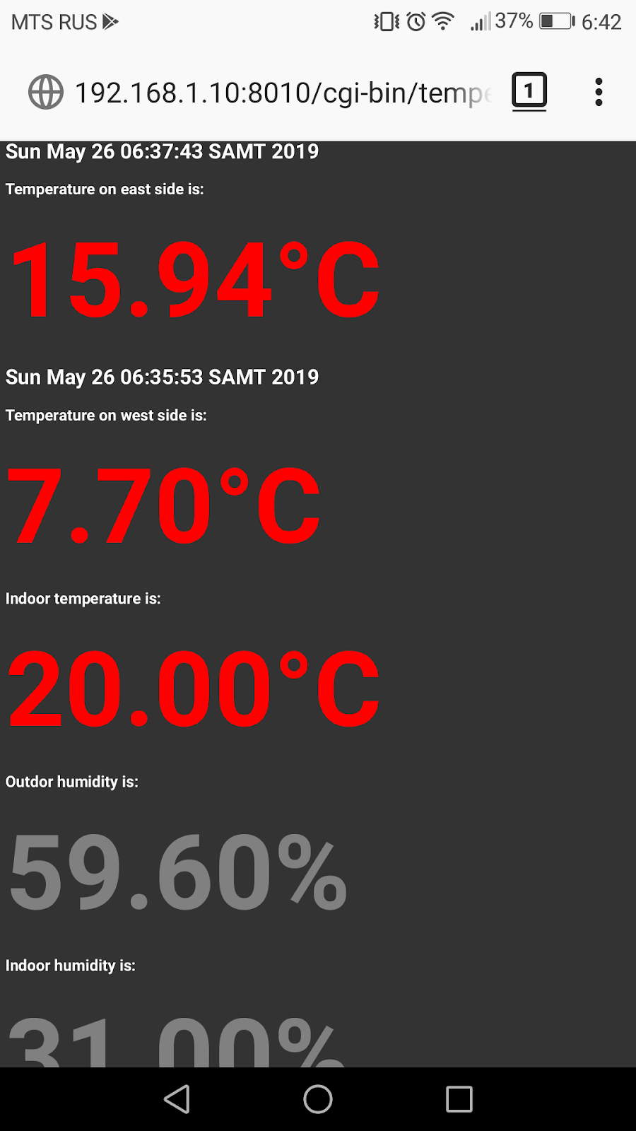
Результат работы последнего скрипта на экране мобильника выглядит так:
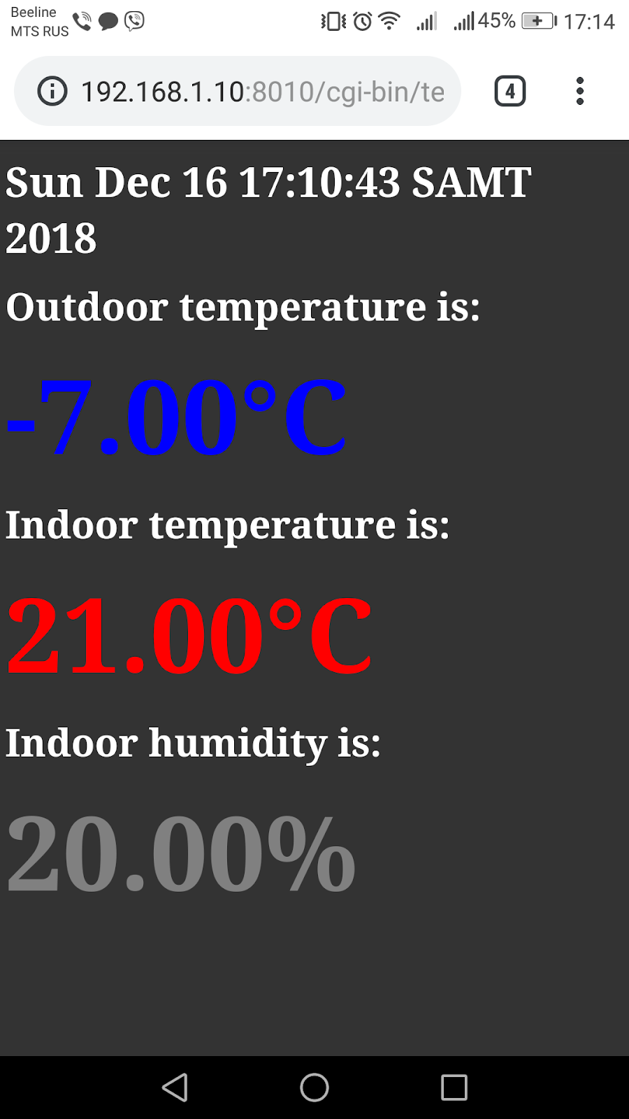
В заключение хочу ещё добавить, что нужно внимательно отнестись к установке датчика уличной температуры. Он должен быть защищён от ветра и прямого солнечного света. Также он не должен напрямую соприкасаться со стеной или окном жилого дома. По моим наблюдениям, расстояние в 10см от стены дома достаточно для корректных показаний.
Способ 2: чтение датчика DS18B20 по адресу
Мы знаем, что каждому DS18B20 назначен уникальный 64-битный адрес, чтобы отличать их друг от друга. В этом методе мы найдем этот адрес для соответствующей маркировки каждого датчика. Затем этот адрес можно использовать для считывания каждого датчика в отдельности.
Что такое температура воздуха?
Это одна из характеристик воздуха, изменяющаяся в зависимости от скорости движений молекул, из которых он состоит: температура растет по мере увеличения скорости и уменьшается при ее снижении.
- Градусы Кельвина (°К). Здесь нулю соответствует показатель абсолютного нуля, при котором движение молекул останавливается (-273,15 °С), поэтому все значения получаются со знаком «+». Этот метод применяется в метеорологии.
- Шкалу Цельсия (°С). Раньше в ней за ноль градусов был принят показатель, при котором тает лед, а ориентиром для значения в 100 °С считался момент закипания воды. Одна сотая разницы между ними соответствовала 1 °С. Сейчас эта шкала является производной от шкалы Кельвина и за ноль принимают 273,15 К, а 100 °С определяют как 373,15 К. Разница в 1 °С и 1 К одинакова, следовательно и значение градуса в этих системах эквивалентно.
- Градусы Фаренгейта (°F), где 1 °F приблизительно равен 1/180 разницы между температурой, при которой тает лед (+32 °F) и кипит вода (212 °F). Эта шкала применяется в США и еще в некоторых государствах.
MQTT functions: disconnect and publish
If the ESP8266 loses connection with the MQTT broker, calls the onMqttDisconnect function that prints that message in the serial monitor.
When you publish a message to an MQTT topic, the onMqttPublish() function is called. It prints the packet id in the Serial Monitor.
Basically, all these functions that we’ve just mentioned are callback functions. So, they are executed asynchronously.
Способ 1: чтение показаний DS18B20 по индексу
В этом методе библиотека Dallas Temperature при инициализации обнаруживает все датчики, использующие одну шину. Она рассматривает всю шину как массив датчиков и присваивает им индексы. Поэтому мы можем точно выбрать каждый датчик по его индексу и прочитать показания температуры.
Вывод вышеприведенного скетча выглядит так:

Рисунок 5 – Вывод показаний нескольких датчиков DS18B20 индексным методом
Schematic Diagram
Wire the DS18B20 to the ESP8266 as shown in the following schematic diagram with the DS18B20 data pin connected to GPIO 4 (D2).

Copy the following code to your Arduino IDE. To make it work for you, you need to insert your network credentials as well as the MQTT broker details.
5) Использование режима энергосбережения DeepSleep
Теперь вместо задержки на функции delay() будем посылать ESP8266 в режим энергосбережения. Для этого нам нужно будет соединить выводы D0 и RST:
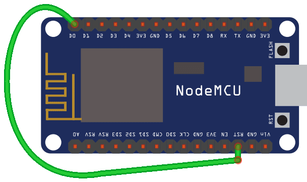
После этого, заменим в главном цикле стоку delay(5000) на ESP.deepSleep(3e7), которая отправит в ESP8266 в режим энергосбережения. Параметр "3e7" означает 3*10^7 микросекунд, т.е. тридцать секунд.
Лог работы программы будет выглядеть теперь так:

Для более корректной работы, мы можем поменять алгоритм таким образом: 1)пусть в начале главного цикла сначала устанавливается WiFi соединение, 2) потом путь передаются данные, 3) после этого WiFi соединение разрывается, и ESP8266 уходит в режим энергосбережения.
Wrapping Up
In this tutorial you’ve learned how to create charts with multiple series to display temperature from multiple DS18B20 sensors. You can modify this project to create as many charts and series as you want and plot data from any other sensors or sources.
Одним из самых больших преимуществ датчиков температуры DS18B20 является то, что на одной шине 1-Wire могут сосуществовать несколько таких датчиков. Поскольку каждый DS18B20 имеет уникальный 64-битный последовательный код, зашитый на заводе, их легко отличать друг от друга.

Взаимодействие с несколькими DS18B20, цифровыми датчиками температуры, с Arduino
В следующем руководстве показано, как подключить несколько датчиков DS18B20 к одной шине и получать показания температуры от каждого из них. Эта функция может быть огромным преимуществом, если вы хотите управлять несколькими датчиками DS18B20, распределенными по большой площади.
Это может показаться пугающим, но, прежде чем углубляться в это руководство, вы должны быть знакомы с основами работы с однопроводными датчиками температуры DS18B20. Если вы не знакомы с ними, посмотрите следующую статью:
А теперь, без дальнейших задержек, давайте подключим датчики DS18B20 к нашей плате Arduino.
DS18B20 Temperature Sensor Libraries
To interface with the DS18B20 temperature sensor, you need to install the One Wire library by Paul Stoffregen and the Dallas Temperature library. Follow the next steps to install those libraries.
1. Open your Arduino IDE and go to Sketch > Include Library > Manage Libraries. The Library Manager should open.
2. Type “onewire” in the search box and install OneWire library by Paul Stoffregen.

3. Then, search for “Dallas” and install DallasTemperature library by Miles Burton.

After installing the libraries, restart your Arduino IDE.
setup()
Now, let’s proceed to the setup() . Initialize the DS18B20 sensor and start the serial communication.
The next two lines create handlers that will allow both the MQTT broker and Wi-Fi connection to reconnect, in case the connection is lost.
Finally, assign all the callbacks functions. This means that these functions will be executed automatically when needed. For example, when the ESP8266 connects to the broker, it automatically calls the onMqttConnect() function, and so on.
Broker Authentication
If your broker requires authentication, uncomment the following line and insert your credentials (username and password).
Finally, connect to Wi-Fi.
In the loop() , you create a timer that will allow you to publish new temperature readings in the esp/d18b20/temperature topic every 10 seconds.
If you prefer the temperature in Fahrenheit, uncomment the following line:
Uploading Code and Files
After inserting your network credentials, save the code. Go to Sketch > Show Sketch Folder, and create a folder called data.

Inside that folder you should save the HTML, CSS and JavaScript files.
Then, upload the code to your ESP8266 board. Make sure you have the right board and COM port selected. Also, make sure you’ve added your networks credentials and the sensors’ addresses to the code.
After uploading the code, you need to upload the files. Go to Tools > ESP8266 LittleFS Data Upload and wait for the files to be uploaded.

When everything is successfully uploaded, open the Serial Monitor at a baud rate of 115200. Press the ESP8266 EN/RST button, and it should print the ESP8266 IP address.
Arduino IDE
We’ll program the ESP8266 using Arduino IDE, so make sure you have the ESP8266 add-on installed.
MQTT functions: connect to Wi-Fi, connect to MQTT, and Wi-Fi events
We haven’t added any comments to the functions defined in the next code section. Those functions come with the Async Mqtt Client library. The function’s names are pretty self-explanatory.
For example, the connectToWifi() connects your ESP8266 to your router:
The connectToMqtt() connects your ESP8266 to your MQTT broker:
The onMqttConnect() function runs after starting a session with the broker.
Schematic Diagram
Wire four DS18B20 sensors to your board.

Uploading the code
With your Raspberry Pi powered on and running the Mosquitto MQTT broker, upload the code to your ESP8266.
Open the Serial Monitor at a baud rate of 115200 and you’ll see that the ESP8266 starts publishing messages.

7) Отправка на web-сервер данных с датчика DHT11 через GET запрос
Теперь нам нужно добавить к получению данных с датчика DHT11, отправку их на web-сервер через GET-запрос, как это делалось в предыдущей статье: Отправка данных от ESP8266 на web-сервер OpenWRT через GET запрос.
Программа в данном случае получается такой:
Для приёма данных, на стороне сервера нужно будет добавить cgi скрипт sensors.cgi следующего содержания:
Данный скрипт записывает полученные показания датчиков в файлы вида: '/site/sensors/"дата"/log.txt'. Файлы автоматически разбиваются по дням. Формат файлов выглядит так:
Чтение показаний датчиков DS18B20 по адресу
Следующий скетч считывает температуру датчиков DS18B20 по их адресам. Прежде чем приступить к загрузке скетча, вам нужно изменить адреса датчиков DS18B20 на те, которые вы определили в предыдущем скетче.
Вывод вышеприведенного эскиза выглядит так

Рисунок 7 – Вывод показаний нескольких датчиков DS18B20 методом адреса
Prerequisites
Before proceeding with this tutorial, make sure you check the following prerequisites.
Handle events
Plot the readings on the charts when the client receives the readings on the new_readings event
Create a new EventSource object and specify the URL of the page sending the updates. In our case, it’s /events .
Once you’ve instantiated an event source, you can start listening for messages from the server with addEventListener() .
These are the default event listeners, as shown here in the AsyncWebServer documentation.
Then, add the event listener for new_readings .
When new readings are available, the ESP8266 sends an event ( new_readings ) to the client. The following lines handle what happens when the browser receives that event.
Basically, print the new readings on the browser console, convert the data into a JSON object and plot the readings on the chart by calling the plotTemperature() function.
10) Второй WiFi термометр на датчике AM2320 (добавлено 26.05.19г)
Спустя полгода после изготовления термометра, должен сказать, что он получился довольно удачным. Это очень удобно, проснувшись утром взять смартфон, и тут же посмотреть какая температура сегодня за окном. Не нужно подходить к замороженому окну и пытаться разглядеть что-то за замороженым окном в темноте.
Теперь же, с приближением лета, возникла необходимость в изготовлении второго термометра. Для чего вам может понадобиться второй уличный термометр? Если у вас окна выходят на север, то вы можете не волноваться за результаты показаний термометра, он скорее-всего будет всегда казать температуру приближенную к реальной. Если же у вас все окна выходят на юг, то даже если вы будете как-то пытаться экранировать сенсор, солнце все равно будет засвечивать его, и показания "поплывут". Если же у вас, как и у меня окна, выходят на восток и запад, то большую часть года вполне можно обойтись термометром на восточном окне. Однако летом, как только встает солнце мой спрятанный под карнизом DS18B20 начинает показывать температуру кипения хлорного ангидрида, что для земной атмосферы несколько ненормально.
К счастью, имеется второе окно на западной стороне на которое можно повесить дополнительный WiFi-термометр. Делать еще один термометр на DS18B20 мне было не интересно, поэтому был куплен датчик AM2320 который кроме температуры еще измеряет и относительную влажность воздуха. Согласно даташиту на датчик: "Digital Temperature and Humidity Sensor AM2320 Product Manual", диапазон измеряемой температуры датчика от -40℃ до +80 ℃, с погрешностью в полградуса. Влажность же он измеряет во всем диапазоне с погрешностью +/- 3 %RH. Датчик может питаться от 3 и 5 Вольт, и может работать на I 2 C протоколе или однопроводному протоколу, наподобие DHT11(не путать с 1-wire).
Я буду использовать I 2 C интерфейс, на ESP12E/ESP12F он расположен на GPIO4 (SDA) и GPIO5 (SCL). На NodeMCU это соответственно выводы D2 и D1:

Подключается датчик к NodeMCU таким образом:

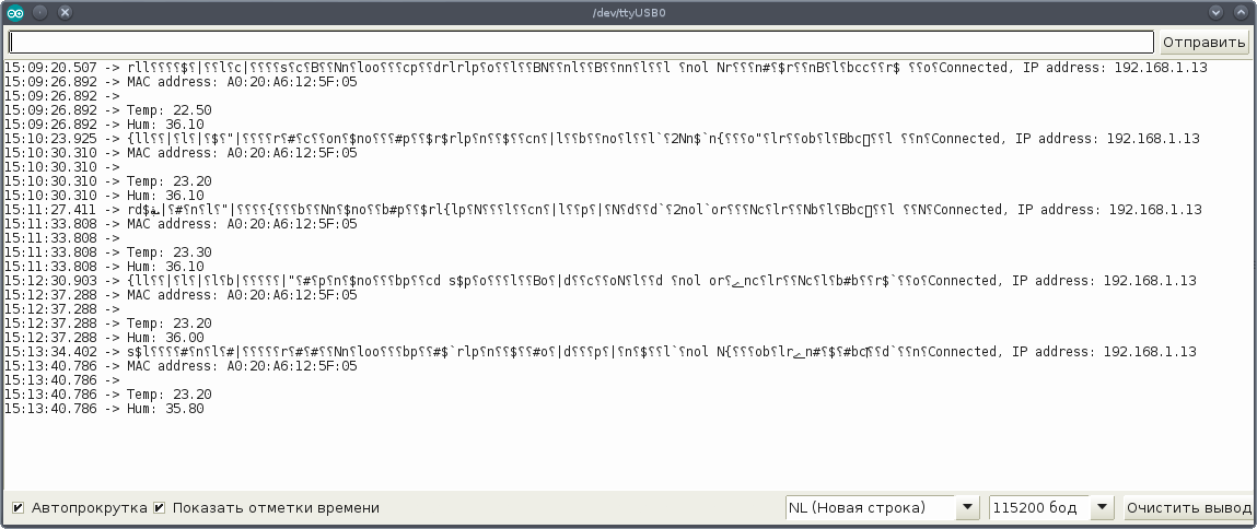
После компиляции скетча и прошивки NodeMCU, в окне терминала мы должны увидеть лог работы:
Остальное - дело техники. Действуя по аналогии с датчиком DHT11, напишем скетч с соединением с точкой доступа, и уходом в спящий режим:
В терминале должен пойти лог такого вида:
Теперь на роутере напишем CGI-скрипт "/site/cgi-bin/am2320.cgi" для приема и сохранения результатов измерений датчика:
Осталось привести скетч ESP8266 к окончательному рабочему виду:
Для отображения данных с двух датчиков, скрипт temperature.cgi нужно будет привести, например, к такому виду:
Выглядит гадко, но это работает. Итоговый результат на экране смартфона:
В заключение хочу немного сказать об автономном режиме работы ESP8266, т.е. режиме работы от аккумулятора. Мне пока удалось добиться беспрерывной работы всего лишь двое суток. НО. У меня довольно "слабый" аккумулятор. Это одна батарея 18650, сама обычная с али. Ее фактическая емкость где-то 500 или 600 мА. Далее у меня не самая эффективная цепь питания. C батареи питание идет на повышающий до 6 Вольт DC-DC преобразователь. Затем питание проходит через понижающий до 3.3 Вольт линейный преобразователь ams1117-3.3. В итоге, я пока имею только двое суток автономной работы. Work in progress, как говорится.
Learn how to publish DS18B20 temperature readings via MQTT with the ESP8266 (NodeMCU) to any platform that supports MQTT or any other MQTT client. As an example, we’ll publish sensor readings to Node-RED Dashboard and the ESP8266 will be programmed using Arduino IDE.

Recommended reading: What is MQTT and How It Works
2) Подключение датчика DHT11 к ESP8266
Теперь нам нужно подключить к ESP8266 несколько сенсоров чтобы впоследствии передавать данные с них через WiFi.
Для начала возьмём популярной датчик температуры и влажности DHT11. Его подключение будет выглядеть так:
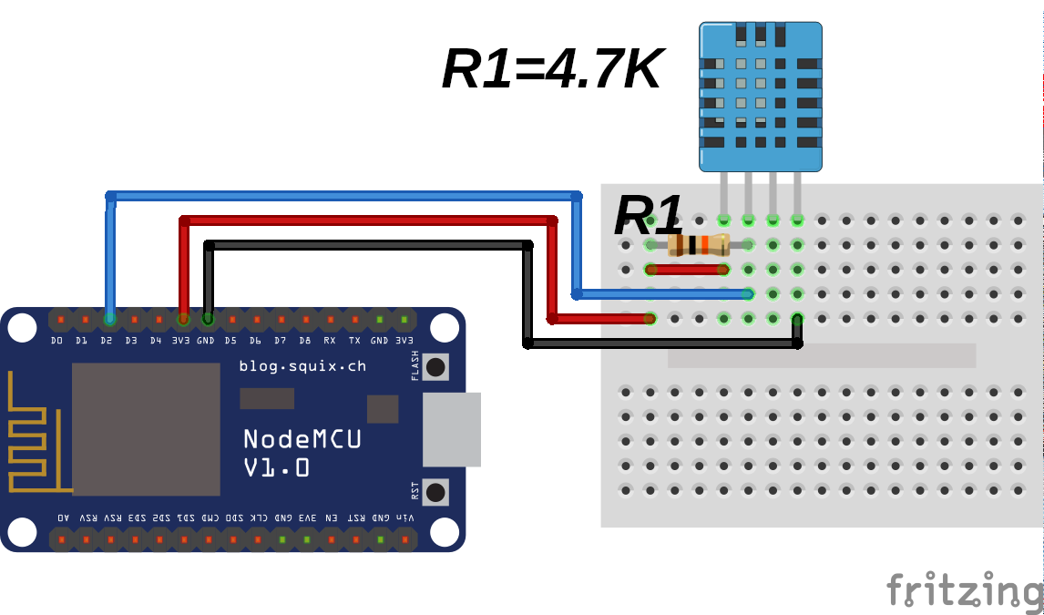
Датчик имеет три рабочих пина: первый пин - питание; второй пин - вывод данных, его следует подтягивать к питанию; третий пин никуда не подключается ; четвертый пин - это земля. Для подтяжки второго пина к питанию я использовал резистор на 4.7К, но т.к. датчик не скоростной, то должны сгодиться резисторы и на 10К или даже на 47К. Датчик может питаться от 3.3 Вольт, что нас вполне устраивает.
После установки библиотек и подключения датчика DHT11 к ESP8266, загрузим в Arduino IDE тестовый скетч:
Если всё было сделано правильно, то после компиляции и загрузки прошивки, в мониторе последовательного порта можно будет наблюдать показания датчика:

Parts Required
To follow this tutorial you need the following parts:
If you don’t have four DS18B20 sensors, you can use three or two. Alternatively, you can also use other sensors (you need to modify the code) or data from any other source (for example, sensor readings received via MQTT, ESP-NOW, or random values—to experiment with this project…)

MQTT Libraries
To use MQTT with the ESP8266 we’ll use the Async MQTT Client Library.
Installing the Async MQTT Client Library
-
. You should have a .zip folder in your Downloads folder
- Unzip the .zip folder and you should get async-mqtt-client-master folder
- Rename your folder from async-mqtt-client-master to async_mqtt_client
- Move the async_mqtt_client folder to your Arduino IDE installation libraries folder
- Finally, re-open your Arduino IDE
Alternatively, you can go to Sketch > Include Library > Add . ZIP library and select the library you’ve just downloaded.
Installing the ESPAsync TCP Library
To use MQTT with the ESP, you also need the ESPAsync TCP library.
-
. You should have a .zip folder in your Downloads folder
- Unzip the .zip folder and you should get ESPAsyncTCP-master folder
- Rename your folder from ESPAsyncTCP-master to ESPAsyncTCP
- Move the ESPAsyncTCP folder to your Arduino IDE installation libraries folder
- Finally, re-open your Arduino IDE
Alternatively, you can go to Sketch > Include Library > Add . ZIP library and select the library you’ve just downloaded.
Demonstration
Go to your Raspberry Pi IP address followed by :1880/ui.
You should get access to the current sensor readings on the Dashboard (gauge and chart).

That’s it! You have your ESP8266 board publishing sensor readings to Node-RED via MQTT.
Поиск адресов датчиков DS18B20s на шине
Следующий скетч обнаруживает все DS18B20, присутствующие на шине, и печатает их адреса на 1-Wire в монитор последовательного порта.
Вы можете подключать только один датчик за раз, чтобы определить его адрес (или последовательно добавлять по одному новому датчику, чтобы вы могли идентифицировать каждый из них по его адресу). Затем вы можете пометить каждый датчик.
Теперь откройте монитор последовательного порта. Вы должны получить что-то подобное:

Рисунок 6 – Нахождение адресов 1-Wire всех датчиков DS18B20 на шине
Скопируйте все адреса, так как они нам понадобятся в следующем скетче.
Creating the Chart
The following lines create the charts with multiple series.
In the next line, define where you want to put the chart. In our example, we want to place it in the HTML element with the chart-temperature id—see the HTML file section.
Then, define the options for the series. The following lines create the first series:
The name property defines the series name. The type property defines the type of chart—in this case, we want to build a line chart. The color refers to the color of the line—you can change it to whatever color you desire.
Next, define the marker properties. You can choose from several default symbols— square , circle , diamond , triangle , triangle-down . You can also create your own symbols. The radius refers to the size of the marker, and the fillColor refers to the color of the marker. There are other properties you can use to customize the marker—learn more.
Creating the other series is similar, but we’ve chosen different names, markers and colors.
There are many other options you can use to customize your series—check the documentation about plotOptions.
You can also define the chart title—in this case, as we’ve already defined a title for the chart in a heading of the HTML file, we will not set the title here. The title is displayed by default, so we must set it to undefined .
Define the properties for the X axis—this is the axis where we’ll display data and time. Check more options to customize the X axis.
We set the title for the y axis. See all available properties for the y axis.
Time Zone
If, for some reason, after building the project, the charts are not showing the right time zone, add the following lines to the JavaScript file after the second line:
Finally, set the credits option to false to hide the credits of the Highcharts library.
Установка библиотеки для DS18B20
Протокол Dallas 1-Wire несколько сложен и требует много кода для парсинга связи. Чтобы скрыть эту ненужную сложность, мы установим библиотеку DallasTemperature.h, чтобы мы могли выполнять простые команды для получения показаний температуры от датчика.
Чтобы установить библиотеку, перейдите в раздел «Скетч»→ «Подключить библиотеку» → «Управление библиотеками…». Подождите, пока менеджер библиотеки загрузит индекс библиотек и обновит список установленных библиотек.

Рисунок 2 – Установка библиотеки Arduino – выбор управления библиотеками в Arduino IDE
Чтобы отфильтровать результаты поиска, введите « ds18b20 ». Там должна быть пара записей. Ищите DallasTemperature от Miles Burton. Нажмите на эту запись, а затем выберите Установка.

Рисунок 3 – Установка библиотеки DallasTemperature в Arduino IDE
Эта библиотека DallasTemperature является аппаратно-зависимой библиотекой, которая обрабатывает функции более низкого уровня. Она должна быть связана с библиотекой OneWire для связи с любым устройством 1-Wire, а не только с DS18B20. Установите и эту библиотеку.

Рисунок 4 – Установка библиотеки OneWire в Arduino IDE
Подключение нескольких датчиков
6) Класс WiFiClient, получение web-страницы от сервера на OpenWRT и отправка данных через GET запрос
Класс WiFiCliet реализует установку TCP соединения с сервером. Демонстрационный пример его использования можно найти здесь: Client — ESP8266 Arduino Core 2.4.0 documentation. Я адаптировал этот пример под свой случай, и в итоге получилось так:
Результат работы программы выглядит так:
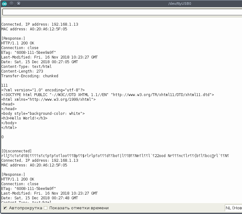
Для контроля можно взглянуть на дамп соединения в Wireshark:

Как видно, соединение осуществляется без ошибок. Красная строчка показывает закрытие соединения клиентом, с помощью вызова WiFi.disconnect().
Теперь аналогично предыдущей статье: Отправка данных от ESP8266 на web-сервер OpenWRT через GET запрос, мы можем отправлять на веб-сервер свои данные через GET-запрос.
Изменим в программе строку:
После чего заново компилируем и перепрошиваем esp8266. Смотрим на результат работы программы:
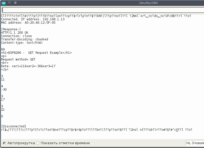
Как видно, данные успешно уходят на сервер.
Prerequisites
Make sure you check all the prerequisites in this section before continuing with the project.
Parts Required
For this tutorial you need the following parts:
Читайте также: